Return to the previous page:
8_inch-a.htm
Completing the partly built 8 inch F 7.8 telescope.
Making a focuser and cutting the eyepiece hole in the Sonotube
 |
History of the 'drain tube focuser'
and adapting the design to make use of 'off the shelf' materials.
Specifications |
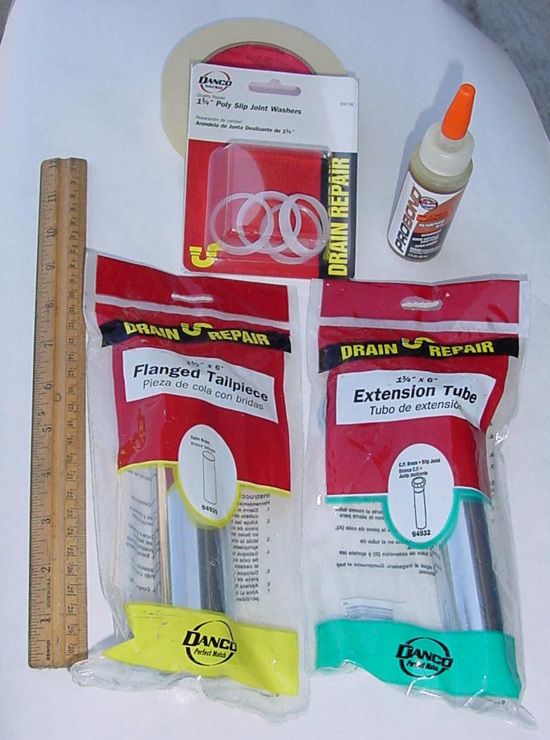 |
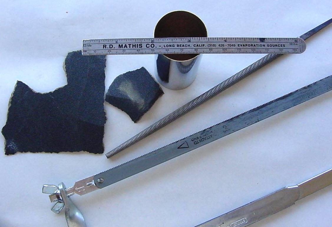
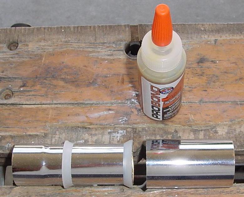
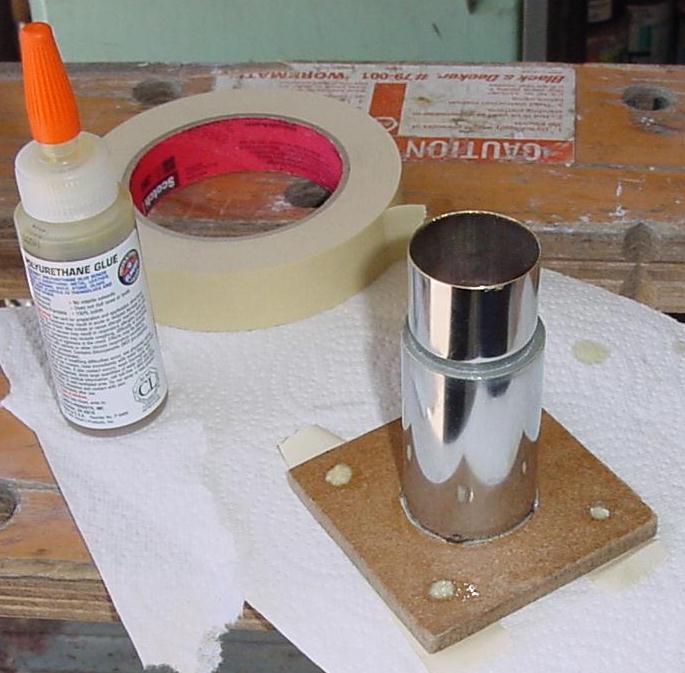
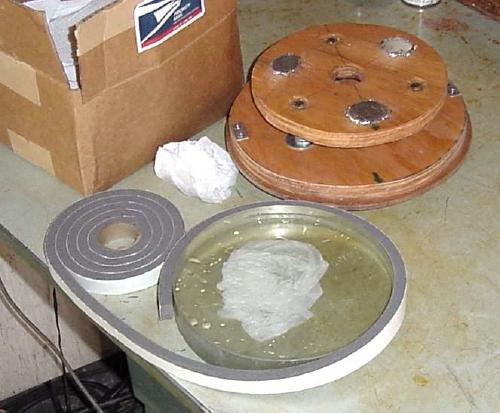
The materials at left will make one drain tube focuser. With the addition of one more extension tube, part 94932, you can make two focusers. |
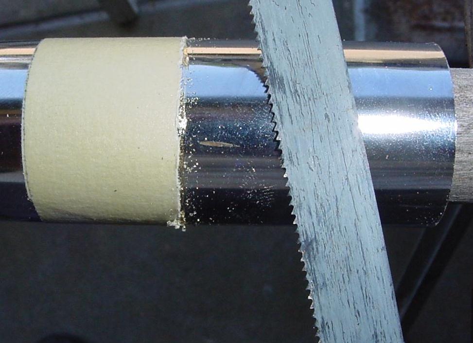 |
Hints on cutting the chrome plated tube.
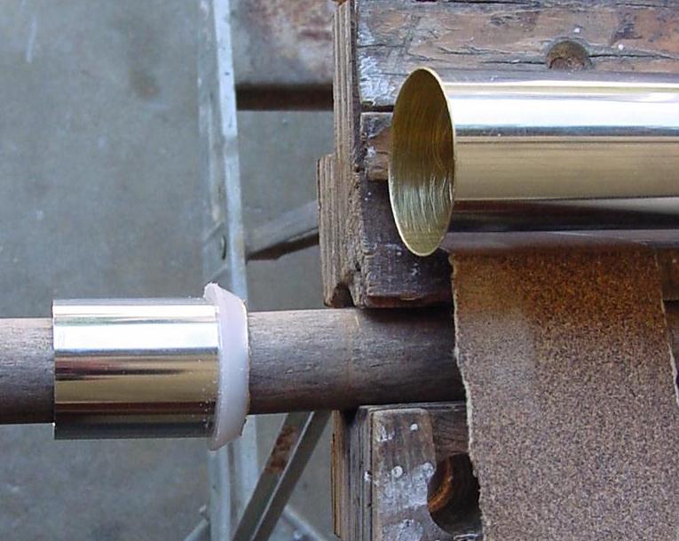
To support the focuser tube while cutting we clamp the remainder of the spider dowel or a broom stick in a vise. After measuring and marking the length we wrap the tube with masking tape to mark the cut line. You will need to carefully guide the saw at first with your finger on the saw's side. Use just 1/2 inch saw strokes. Work around the tube. After about twice around you will be through the chrome and into the brass and then it is much easier to maintain the cut. When the saw starts to break through it will grab. Keep rotating the tube and go lightly. |
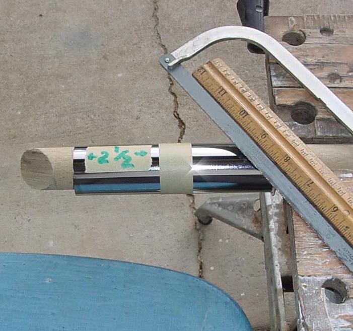 |
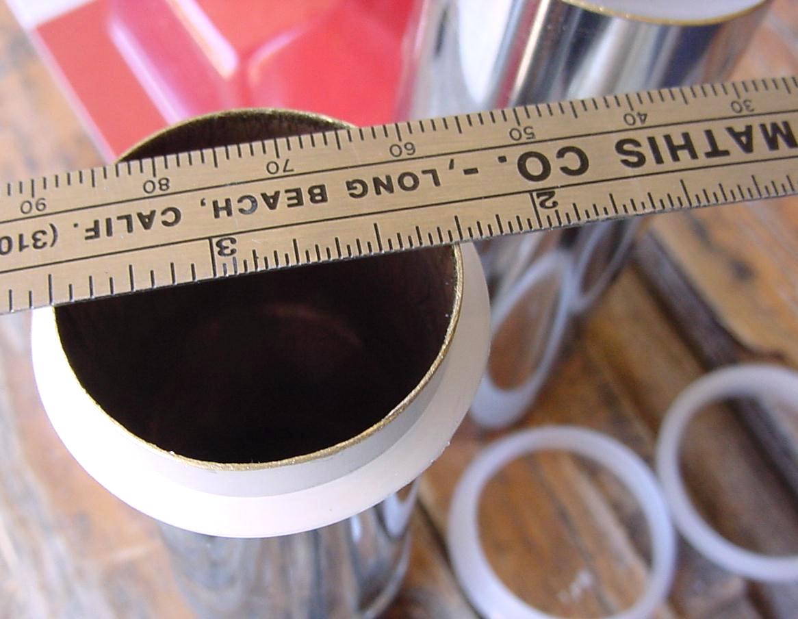
Ready to cut the larger tube to the proper length. |
 |
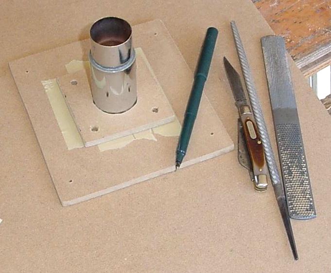
File lightly then sand to remove the burr from the cut without damaging the chrome plating on the tube. |
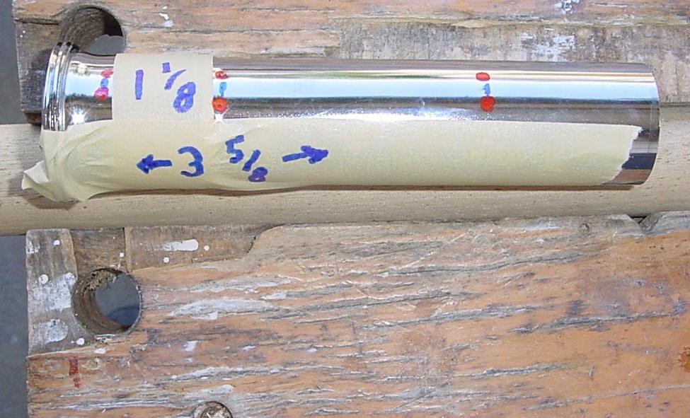 |
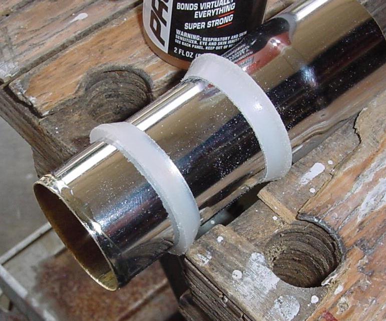
The 'Extension Tube' has two diameters. Find the last bit of small tube before the tube expands and make a mark. From that mark measure 1 1/8 inch toward the large end of the tube and make a second mark and wrap the tube for a cut at that point. Then measure back toward the small end of the tube 3 5/8 inches to locate the cut line for the small end of the tube. |
 |
After sanding the burr on the small tube we find a seal from the package containing four seals will just slip over the small tube. |
 |
With the seal on the small tube to hold its shape we sand the outside of the seal with 100 grit sand paper and rotate the tube as we sand. After a bit of sanding test it in the larger tube. When you can just press the seal into the larger tube switch to 240 sand paper and continue to sand lightly to finish. Although a press fit may seem adequate it will be found that on cold nights the seal will harden and produce too much friction. So sand until the seal will just slip through the outer tube with no friction and then stop. |
 |
Get another seal from the package of four seals and slip it into the sharp burr on the end of the large tube that we cut off. Sand the inside of this seal until the smaller focuser tube will just slip into the seal. This will require more sanding because the seal is wider on its inner surface. When you test for fit take the seal out of the burred tube and slip it into the outer focuser tube to get a proper measure of the fit. As before stop when there is no more sliding friction due to compression of the seal.. |
 |
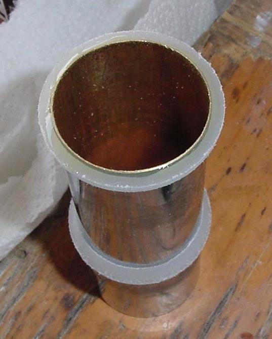
Here is a view of the assembly before gluing. The seal on the right will be glued to the inner tube first. The seal on the right has been carefully sanded to just slip in the outer tube. Before you glue the right seal be sure the seal on the left has been put onto the inner tube correctly. If the left seal is not on the tube when you glue the right seal you will have to start over. The glue can be removed with alcohol before it sets. After it sets sandpaper is about the only way to remove it. |
 |
Here you can see the glue I have carefully applied to the end of the small tube. Best to do this when your hands are rested. Otherwise you might shake and get the glue on the sliding bearing part of the tube. There is a bit of sanding dust on the tube. I should have cleaned the tubes before gluing but it worked out anyway. |
 |
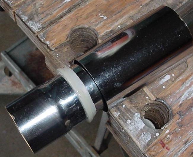
Here I carefully slip the seal on the inner tube until it is just short of the tube end. If you stop just short of the tube end the glue will form a bead between the seal and the end of the tube. Best to do something else for about five or six hours to let the glue set. |
 |
Here I have applied the glue to the seal that is to
slide on the inner tube. If you get glue on the sliding section of the
inner tube then you will be tossing this one in about six hours. Carefully
slide the seal into the end of the outer tube then sit the assembly
upright on the large end of the small tube to cure.
After six hours we test our work and it works fine. With the focuser extended I add a tiny bit of silicone vacuum grease to the inside of the outer tube and it slides like a dream. The flared part of the inner tube is slightly larger than the 1 1/4 inch sliding barrel of the eyepiece tube. So you will need to wrap about two turns of vinyl electrical tape to the outside of your eyepiece. Or possibly the tape could be applied to the inside of the focuser. Another possibility is to put the end of the flare onto the dowel and dimple the focuser tube slightly with a center punch. I didn't try this. It would take two people and about 15 minutes careful work with the center punch. If not done carefully the inner bearing might be warped. We recommend making the tilt adjuster at this time. |
Next we will need to cut the hole in the Sonotube. |
|
 |
Since we will be mounting a plate on the
Sonotube into which to mount the focuser instead of just cutting a round
hole in the tube we will have more range for adjustment or modification
later. Our first mounting of the focuser onto the plate did not
have a tilt adjustment. I just cut a hole in the plate for the focuser
and used a piece of paper to point the focuser tube at the diagonal then
glued with silicon sealant. To collimate a
Dobson spider you slide the legs on the inside of the Sonotube which
unfortunately shifts the diagonal around the center axis of the Sonotube.
I later had to cut the sealant and re-glue the focuser. Although the
telescope worked without a tilt adjuster the tilt of the focuser was still not correct.
The calculations below will be for the design that used the tilt adjuster. We will build the tilt adjuster further down the page. |
 |
When focused at infinity, looking at a distant star, the focuser should not be at its most inward adjustment because different people will need a different focus to correct the natural magnification of their eye. So although the eyepiece shoulder is 2 7/8 inch above the Sonotube at the most inward adjustment I will slide the focuser out 3/8 of an inch until the eyepiece shoulder is 3 1/4 inch outside the Sonotube. With masking tape I tape the focuser at this adjustment. |
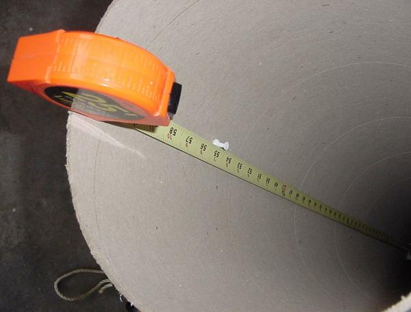 |
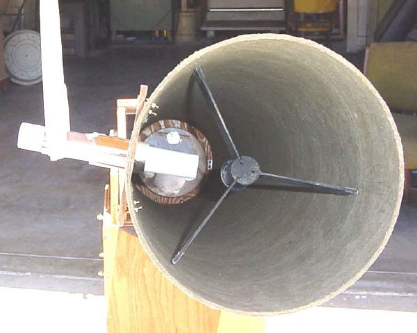
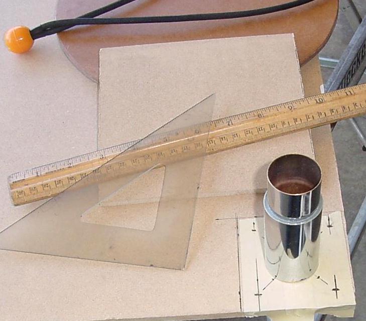
The distance from the mirror to the prime focus is 62 1/2 inches. The diameter of the outside of the Sonotube is 10 1/8 inches or a radius of 5 1/16 inches. The prime focus will be 3 1/4 inch outside the tube so 5 1/16 plus 3 1/4 equals 8 5/16. So the hole in the tube will be 8 5/16 short of 62 1/2 or 54 3/16 inches up the tube from the mirror face. In the picture at left I measure up the tube from the uncoated mirror face and stick a push pin though the tube at 54 3/16 inch. |
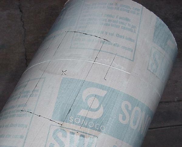 |
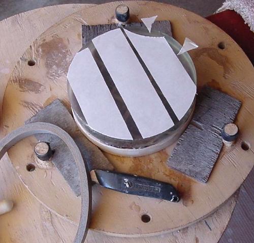
We cut a couple of pressed board plates to go on the tube in case the design changes. The plates are 6 1/2 inches in the tube length direction and 6 inches in the tube diameter direction. Here we lay out the hole on the outside of the tube using the point of the push pin as the center of the hole. The hole will be 6 1/2 x 3 inches. If you have trouble laying out the hole on the curve of the tube then lay it out on a sheet of paper and tape the paper to the tube. We cut the hole with a utility knife. |
 |
After cutting the hole I tapered the edge a bit by removing a couple of layers of the layered tube on each side of the hole. This lets the plate sit better on the curved tube. After mounting the plate on the tube if the focuser is not pointing at the diagonal you can trim the top or bottom of the hole. Later the edges of the hole will be painted with polyurethane paint to harden the cardboard. Here the camera captures the prime focus image of a street light. |
 |
With the eyepiece taped into the focuser and the focuser adjustment taped at 3 1/4 inches ( 3/8 inch from all the way in ) I focus the telescope on a distant hill by moving the spider in the tube until the focuser focuses at the proper height above the tube. Make a mark on the tube above the focuser. If we did the calculations correctly the mark should be above the center of the hole. If not either the calculations are wrong or we are not holding the eyepiece assembly correctly. If the calculations are wrong we will cut the hole in the plate further up or down the tube to compensate. If that is also wrong there is yet lots of pressed board to make more plates. |
 |
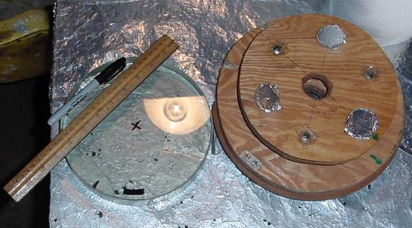
Here we are laying out the focuser hole location on the plate. The holes that mount the plate on the Sonotube are 3/4 inch in from one edge and 1/2 inch in from the other edge. |
 |
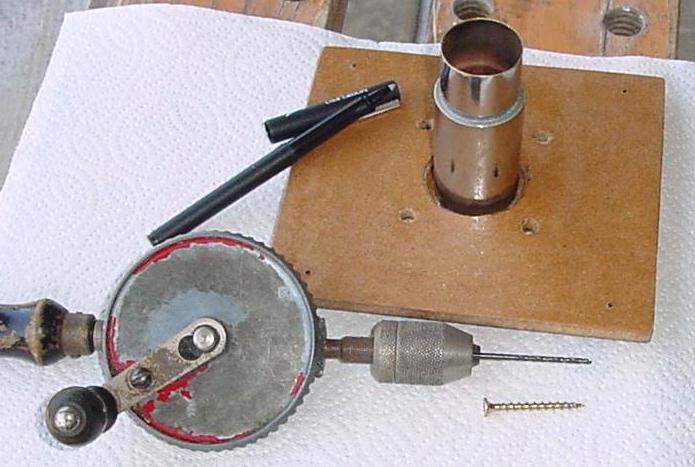
And now we have drilled holes to make the
focuser hole in the plate. The 1/4 inch thick pressed board is available at Home Depot. |
 |
And here is one last chance to adjust the focuser by sliding it in or out of the plate before gluing with sealant. This is the version without the tilt adjuster. |
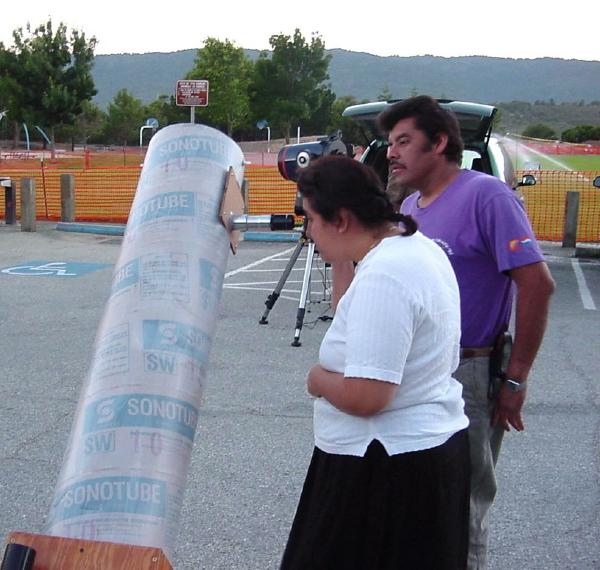 |
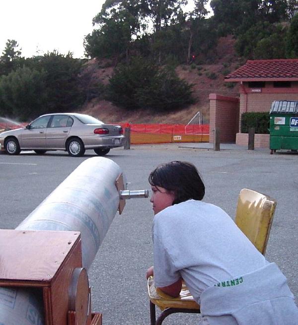
Here is first light for the telescope at a star party using the uncoated mirror on the moon. |
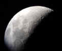 |
This is a picture through the telescope. Its a bit fuzzy but most of the problem is due to heat waves caused by marine advection. Its just after sunset and the ground and the telescope are still warm. The scope is capable of better than this even with the uncoated, un-figured mirror. |
 |
Here we test the telescope for the first time using a traffic light LED as an artificial star and a Ronchi grating. |
 |
The picture is taken with the grating
inside of focus. If the lines were perfectly straight then the mirror
would be a paraboloid which is the desired curve for our mirror. Since the lines widen
slightly just inside the edge then that zone of the mirror is focusing closer to the mirror or
in this case also closer to the grating. I suspect that the mirror is
near to spherical since there is very little difference between an ~F 8 sphere
and an ~F8 paraboloid.
At the mirror edge the lines turn inward indicating a mild ( well, I thought it was mild ) turned down edge. The bottom part of the image is vignetted, probably by the diagonal. |
 |
Adding the tilt feature to the focuser |
 |
The holes that mount the 6 1/2 x 6 inch
plate to the Sonotube are 3/4 inch in from the edge in one direction and
1/2 inch in from the edge in the other direction. The holes are drilled
at a slight angle so the 1 inch x 6-32 mounting screws will go more or
less straight through the Sonotube. Once these holes are drilled the
plate has an inside and an outside and a top and a bottom so best put an
index arrow showing the top and inside.
The small pressed board plate is 3 1/8 x 3 1/8 inches. The holes in the corners are 1/2 inch in from the edges. When tracing around the focuser keep in mind that the focuser will be glued to this plate so the focuser hole should not be oversize. |
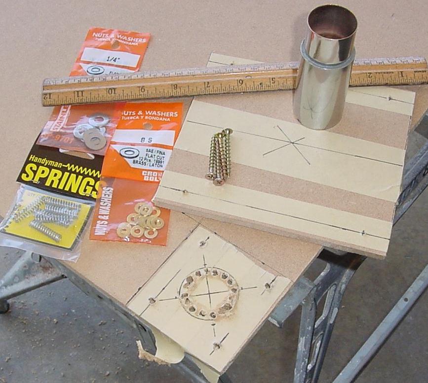 |
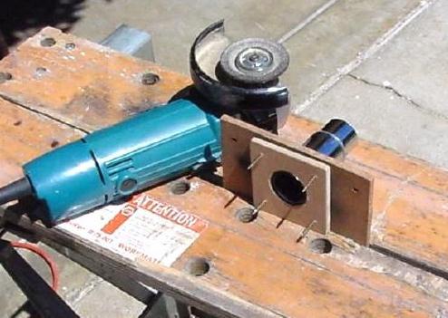
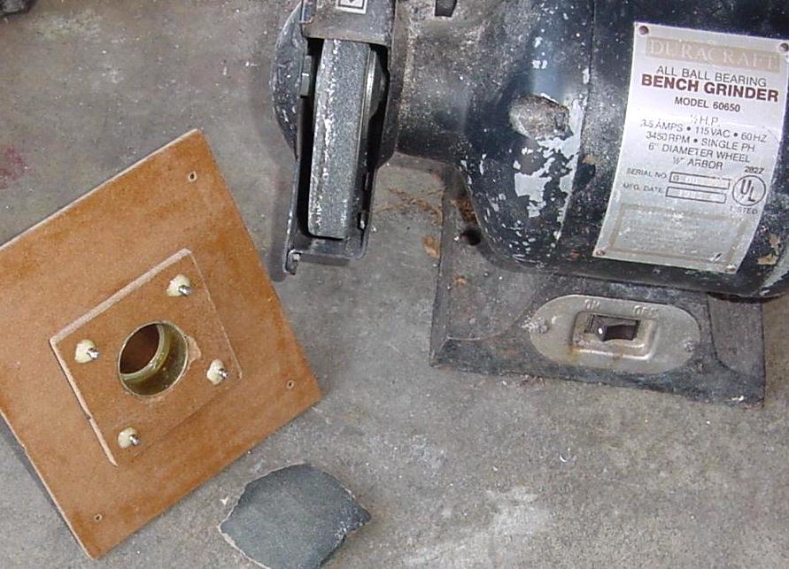
Here are the parts for the focuser tilt
feature. These springs are twice too long and we cut them using the
bench grinder to save our wire cutter pliers. If you are not good with
power tools Ace Hardware has springs the proper length without cutting.
Again, safety is your
most important responsibility.
The #6 x 1 5/8 inch deck screws are left over from the construction of
the telescope structure. The flat 1/4 inch washers are small enough to just
catch the head of the deck screws.
You may notice that I mistakenly drilled the holes through the 3 1/8 x 3 1/8 plate too large while making this focuser tilt plate. The holes were supposed to be undersize for the screws to tap. |
 |
The focuser tube hole through the larger plate will be 1/4 to 3/8 inch larger than the focuser tube. Be sure the holes on the two plates are aligned when testing the fit. |
 |
To avoid future problems I put an index arrow on both the small plate and the large plate. Then painted with polyurethane stain. Wait over night before gluing. |
 |
Here I fill the oversize holes in the 3 1/8 x 3 1/8 plate with papier-mâché made from paper towel and polyurethane glue. This step added 5 hours waiting time while the glue cured. The filled holes are much tougher than the original pressed board. |
 |
This time I drill the holes in the small plate the correct size. |
|
Grinding away the excess screw length. Grinding makes the screw hot enough to burn the pressed board so go slow. After grinding remove the burr on the end of the screw with sand paper or a small file. The version without the papier-mâché can be dipped in polyurethane stain to harden the hole in the pressed board. The eyepiece tilt adjustment won't be adjusted often so you might grease the screws slightly to keep the polyurethane from sticking to the screw over time. |
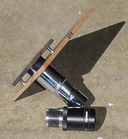 |
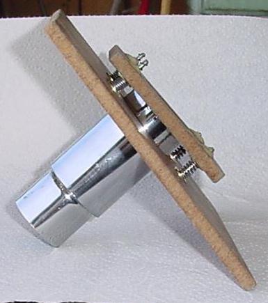
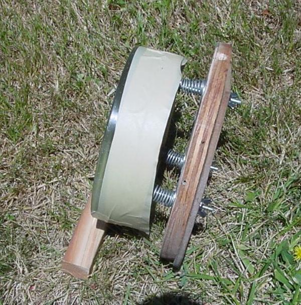
Here is the completed focuser with the tilt adjuster. Two turns of electrical tape on the eyepiece barrel made for a nice fit. If you use a Barlow then put the tape on the inside of the focuser tube so you won't be moving the tape when the Barlow is in use. |
| |
This picture shows the tilt adjustment at full tilt. More than enough adjustment range. |
 |
When spraying with black primer be sure you
are away from cars and buildings. It is safer to spray when there is no
wind. Move the can continually to spread the paint and avoid making
drips of paint. If you get a run then wipe it off and spray more in a
few minutes. In this picture the focuser is intentionally all the way in
to avoid spraying the sliding bearing. Also we masked the inside of the bell where
the eyepiece will be. After the paint is dry renew the index
arrows.
This is a good time to spray the top 18 inches of the Sonotube
black. The inside of the Sonotube tube opposite the focuser is the area
most likely to reflect stray moonlight or street light into the
eyepiece. |
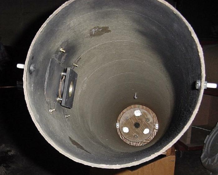 |
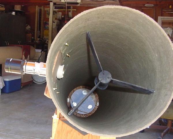
After doing a test collimation I find the
spider legs slip too easily on the inside of the Sonotube. So I put a
bit of silicone where the legs will be to increase the friction.
Also we added the nylon bolts for the bungee strap that holds the tube cover onto the tube. |
| The Telescope tube is now complete | |
 |
We are now reasonably certain of the tube balance point so we can shorten the structure to reduce the overall height and make the scope easier to transport and less top heavy. We decided to remove 5 1/2 inches which still left about two inches minimum clearance. If you add anything heavy to the top of the tube this clearance will disappear when the tube is re-balanced. So don't cut it too close or you may be adding weights or springs to re-balance. As it turned out 2 inches was not enough clearance. After a later modification we had to raise the cradle boards and replaced the 3/8 lag bolt with a through bolted carriage bolt with 3/8 inch steel/nylon friction nut so it could be left slightly loose. |
 |
Here we are re-drilling the holes in the now cut down structure. We sanded and painted on more polyurethane stain to finish the job. |
BACK to 8_inch-a.htm
BACK to alt_11.htm
BACK to alt_12.htm
Figuring the 8 inch F 7.8 telescope mirror
|
This is our Ronchi picture using the artificial star. Although it is easy to use visually it is very difficult to photograph. So I decided to use the tester and test at the radius of curvature at least for the initial part of mirror figuring. I noted that a large part of the seeing problems are at the telescope or within 200 feet of the telescope. |
|
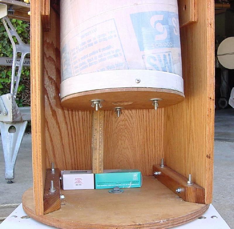
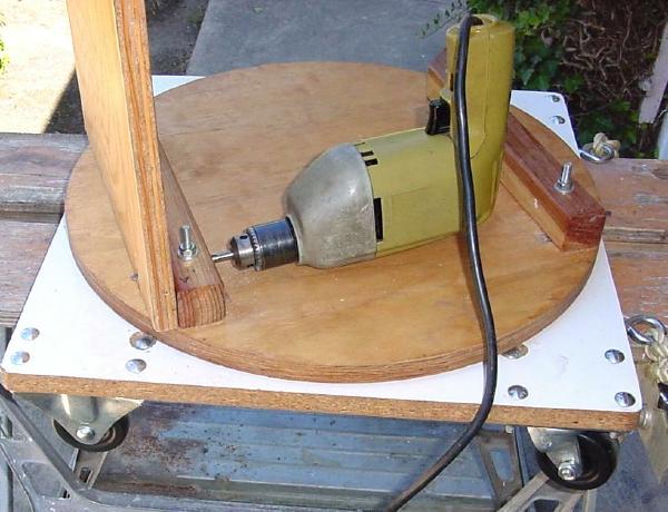
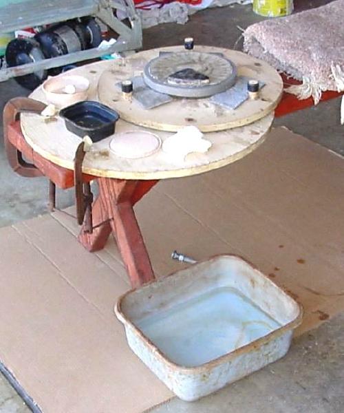
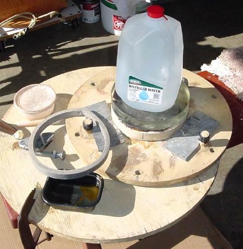
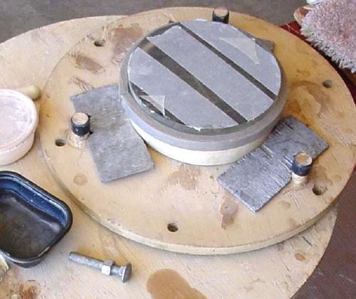
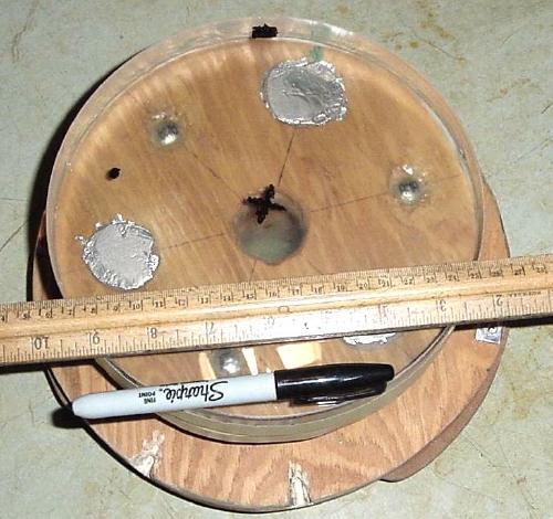
In this picture I have set up the tester and removed the spider from the telescope. The Dobsonian base and the tail gate bolts make it easy to adjust the mirror tilt. A board on the scope compensates for the absent weight of the spider and eyepiece. The camera captures the image of the reflected tester light. |
|
|
I started the Ronchi program Java applet to produce a simulated Ronchi picture. After setting the mirror diameter to 8 inches and the radius of curvature to 125 inches I adjusted the 'grating or knife edge position' to get the five vertical bars. After plotting I captured the picture with PrintKey. This picture will be our reference while testing at the radius of curvature. |
|
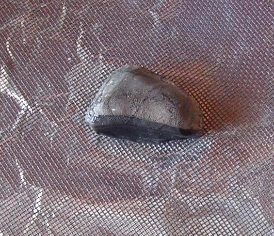
Here is the mirror as it was before any figuring. The
top picture is inside of the center of curvature and eventually will
need to look like the simulated picture. The
bottom is outside of the center of curvature. The turned
edge shows up well outside of focus. ( Outside of the center of
curvature. )
If you are interested in taking Ronchi pictures I found the blur/sharpen feature of Microsoft PhotoDraw does a good job of sharpening the Ronchi picture. |
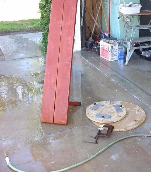 |
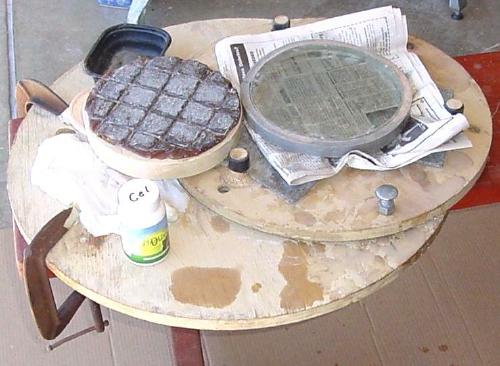
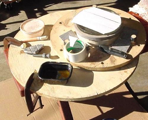
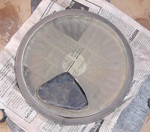
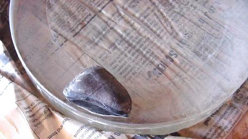
Before stating to polish again I hose down the polishing bench. |
 |
Since I know the edge is turned I make a sweat band to keep the edge cool. With the low amount of expansion of Pyrex with heat this will only help a little. But the area it helps is right at the very edge, an area that is difficult to control. |
 |
Using a very bright light and reflecting it so the light just misses my eye I have found the mirror edge is still scattering light. So the mirror that worked fine on the moon will probably look frosted at the edge after coating. So being a bit of a perfectionist I decide to polish more at the edge and put off figuring. Here I use the weegee lap for a half hour working around the edge. Checking the edge again I can still see the scattered light and I picked up a few tiny scratches too. Possibly the weegee lap had a tiny grit stuck to it or the CeO pot might be contaminated. I clean out the CeO pot and resolve to press the weegee lap before polishing next time. |
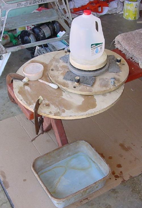 |
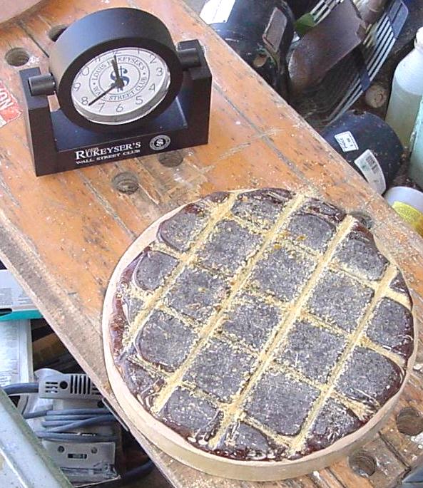
Here I press the lap
on top of the mirror. I hosed off the water jug too.
Next I polished with lap on top for one hour with a wide 'W' stroke. 1 1/2 to 2 inches overlap. The mirror looks very polished but I can still pick up the scattered light using a bright light reflected as before. Possibly the edge did not get its full share of the finest grinding grits. |
|
Not a lot of change in the Ronchi pictures. But then using a long stroke with the lap on top what would one expect? |
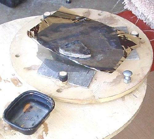 |
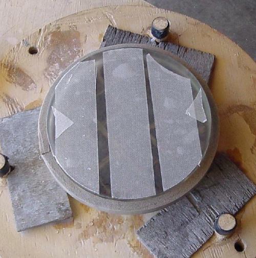
Here I textured the weegee lap with plastic window screen. This should speed up the polishing speed. I covered the mirror with foil so the mirror never got wet. The mirror was heated in the pan of water as usual. The weegee lap was heated in the black pan for 45 seconds in water in the microwave. I pressed the lap into the screen for about a minute with the palm of my hand. |
 |
Here is the texture. |
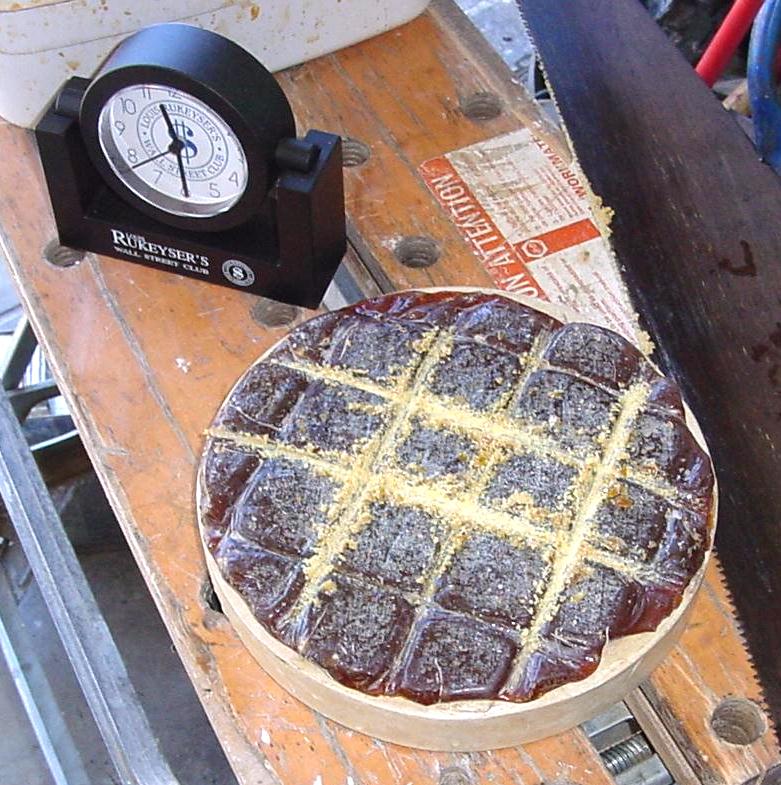 |
Time to trim the pitch lap again. If you don't heat the lap under hot water for a few minutes first before sawing then expect big flakes to break out of the facets. |
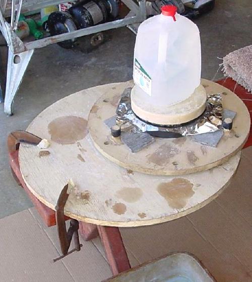 |
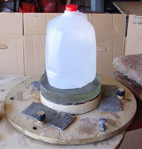
Here I texture the 8 inch lap with the screen. The
water bottle is not enough weight. Put your knee on it for a couple of
minutes.
Before polishing do a light press. |
 |
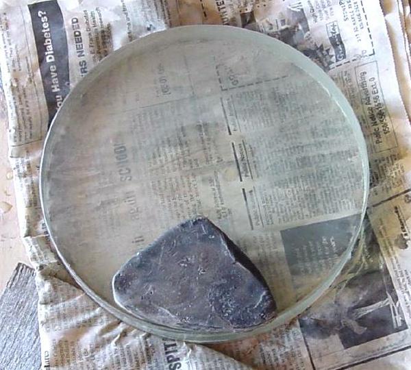
If the mirror slides around while polishing then put
wet
newspaper under it.
I polished for 30 minutes hard with the weegee lap tangent to the mirror edge and extending 1/4 inch over the edge at each end of the stroke. Looking at scattered light from the very bright light I can still see scattering at the last 3/16 inch at the edge. This area is 95 percent polished but the un polished areas appear mottled. The tiny scratches I got before are fading. Next I polish one hour with the 8 inch lap on top with the sweat band with 1 1/2 to 2 inch overlap 'W' stroke as before. The situation at the outer 3/16 inch of the mirror is now more clear. There appears to be the bottom of the rough grit pits randomly every 1/50 of an inch or so. The edge looks completely polished unless I get the light just right. Its time to decide whether I'm making a mirror as jewelry or making a telescope. This type of defect won't be noticeable in the image so I decide to move ahead with figuring. |
|
|
|
|
Using the weegee lap with a bit of overhang at the end of the strokes seems to help soften the hump just inside of the turned down edge. |
 |
I polished for 30 minutes hard with the
weegee lap tangent to the mirror edge and extending 1/4 inch over the
edge at each end of the stroke as before. Looking at scattered light from the very
bright light I can still see the bottoms of pits the last 1/8 inch at the
edge and a few scattered pits further in.
After this hard polishing wait a minute before trying to lift the mirror to rest your hands. In the picture I'm doing a light press before polishing with the mirror on top. |
 |
With the mirror on top and the sweat band there is
little room to wrap my warm fingers over the mirror edge so I put down
double side rug tape on top. This worked well. I used a narrow 'W'
stroke for one hour with 3/4 inch overlap on the sides and one inch overlap
on push and pull. This type of stroke is supposed to bring the edge up
and flatten the mirror center. The reverse of the parabolizing stroke.
After starting I soon moved out of the sun because the sun was heating the pitch at the edge causing the mirror to grab. |
 |
Inside of focus the picture looks about the same. |
 |
Outside of focus we can see the mirror center is focusing more distant from the mirror and nearer to the grating. This is the opposite of a paraboloid. In a paraboloid the center would focus closer to the mirror and farther from the grating when testing outside of the 'radius of curvature'. The oblate figure is easy to fix. The main objective now is to fix the turned down mirror edge. Of course I could just go ahead and parabolize and mask the edge after coating but I'm stubborn. |
|
Next I polish for 30 minutes with the weegee lap with no over hang. I
used my finger as a guide along the mirror edge. Then the narrow 'W'
stroke as before for one hour with 3/4 inch overlap on the sides and one inch overlap
on push and pull. Hopefully the area inside the edge is getting
lower and the slightly pitted edge is staying the same.
The marking pen marks seen in the Ronchi picture seem to indicate the shoulder where the turned down edge begins is about 1/2 inch in from the edge. |
 |
Its Friday and the Telescope Makers Workshop meets tonight so I decide to get their analysis. One of the people there suggested the wok to remove the edge. Well, if I remove this edge there will just be a smaller diameter edge so why bother? The other possibility is to mask the existing edge after the mirror is coated. By then I will know how much of the mirror is serviceable. After they understood I wanted to try to save more of the edge they suggested first smoothing the mirror so I could get a better reading of the figure. |
|
First I trim the lap again and press. Lap on top for 15 minutes with a 'W' stroke. Light pressure, one inch overhang on the sides and 1 1/2 overhang on the push pull. Then mirror on top for 30 minutes of smoothing stroke. One inch overhang on the sides and 1 1/2 on the push pull. The day is warming to near 90F and the mirror is beginning to grab. I was able to press my hand into the rug tape then lift up slightly during the stroking to stop the grabbing. |
 |
Still working on the turned edge. 30 minutes heavy pressure 1/8 to 1/4 inch inside the mirror edge with the weegee lap. Then 15 minutes full size lap on top, light pressure, narrow 'W' stroke, 3/4 overlap on sides, 1 to 1 1/2 inch on the push pull. Then 30 minutes smoothing stroke same as last time. |
 |
Decide to use a black pen for marking. Also added a mark at the 70 percent zone this time. Mirror radius, 4 inch times .707 = 2.828. Or about 2 and 3/4 plus 1/16 inch. |
 |
Here is a Foucault test. The knife edge is on the left so using the rising sun illusion the light is from the right. The inner edge of the weegee lap has made a low zone at about the 40 percent zone. Or the alternate interpretation, hill in the center. |
 |
Is the turned edge getting better? It must have become very turned while I tried to polish out the edge. |
 |
|
 |
Its August 27, 2003 and Mars is at its closest. This is the star party at College of San Mateo. The 12 1/4 inch on the left focuses on the LED with an eyepiece while the 8 inch project scope on the right has the Ronchi grating. |
 |
Back to polishing. 45 minutes on the lazy Susan guiding the weegee lap around the edge with my finger. Then 30 minutes smoothing stroke with the mirror on top and the sweat band. |
 |
|
 |
It appears to me that the high point inside the turned edge is about 1/4 inch in from the edge. |
 |
I found half the mini weegee that had broken in half on the floor. After trimming I texture it with plastic screen. |
 |
45 minutes with half of mini weegee guiding along the edge with my finger. Heavy pressure. This is drastic but I'm getting impatient. 15 minutes with full size lap on top. 30 minutes smoothing stroke as before. Slightly wider 'W' to reduce center hill. |
 |
The center hill is gone and finally the elusive turned up edge appears. Actually its still turned down at the very edge. The focal length 1/8 inch in from the edge seems to be the same as the mirror center area. Since I am willing to mask off the outer 1/8 inch of the mirror the turned down edge has probably been conquered. |
 |
Its uncertain how deep the cupping and unevenness is where the mini weegee polished. Getting the outer 25 percent smooth again will be the next project. |
  |
45 minutes with weegee lap guiding along the edge with my
finger.
15 minutes lap on top 'W'. 3/4 inch overlap on the sides. 1 1/2 inch on the push pull. Hot day, near 90F now. 30 minutes with the mirror on top. Smoothing stroke. Light pressure to avoid grabbing. 'W' with one inch overlap on sides and 2 inches on the push pull. In the picture I am applying the rug tape as before in preparation for polishing with the mirror on top with the sweat band. |
 |
The marker pen band at the edge is 1/4 inch wide and 1/4 inch in from the edge as before. |
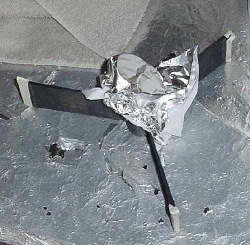 |
Since the Mars star party the spider has been in the scope. We always wrap the diagonal in layers of lens paper or Kim Wipe and foil when it is out of the telescope. |
 |
Turned down edge seems to show up better outside of
focus. But now we have turned up edge and turned up edge seems to show
up better inside of focus. Seems the smoothing with the larger
weegee lap has also improved the remaining turned down edge in the outer
1/8 inch of the mirror.
The highest zone (shorter radius zone) appears to be between 1/4 and 1/2 inch from the mirror edge. The radius of curvature is still 125 inches. |
 |
More of the same polishing with the weegee a bit further out might flatten the high zone. The weegee seems to polish very little on its outer 1/4 inch so we will try polishing with the weegee extending over the edge of the mirror a bit and hope to avoid getting the turned edge again. |
 |
30 minutes, weegee lap extending over the edge 1/4 inch
on the push stroke.
15 minutes lap on top as before using 3/4 inch overlap on the sides. 1 1/2 inch on the push pull. 30 minutes with the mirror on top. Smoothing stroke. 'W' with one inch overlap on sides and 2 inches on the push pull. |
 |
Inside |
 |
Outside |
 |
I try a knife edge test to try to understand the fine detail in the Ronchi pattern. The mirror seems to be oblate with a slight high zone at 70 percent. The marker pen mark at the 70 percent zone locates the mirror zone easily. The edge still looks turned. Its time to start testing the parabolizing stroke. |
 |
Time to touch up the pitch lap with the carpenters saw again. Don't forget to wash and dry the saw first if it is dirty. If I hadn't heated the pitch lap under the hot water faucet first there would have been big flakes missing from the facets now. |
 |
After washing the pitch lap under cold water to get rid of the pitch dust I heat the mirror in the plastic pan and heat the pitch lap under the hot water faucet and do a light press. When I placed the mirror face down on a paper towel on the table to mark on the back with the marking pen I picked up a small half circle scratch on the mirror face near the edge. A single sheet of paper towel on the table was not enough padding. |
 |
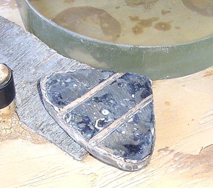
The mirror has a four inch circle on the back.
The parabolizing stroke starts with the four inch circle over the edge
of the pitch lap. Using a modulated 'W' stroke I polish across the
mirror until the four inch circle on the back of the mirror is over the
other edge of the pitch lap. See the animated picture. Then polish back
across the lap to the starting area.
The four inch circle on the mirror back never goes beyond the edge of
the pitch lap. During the last inch of each push stroke I rotate the
mirror about 10 or 15 degrees. Note, in the thumbnail picture the mirror has
been left overhanging the pitch lap. This is not good because in a few
minutes the mirror will press a ridge into the pitch.
I polished across and back twice at each of the six positions of the lazy Susan. And continued light polishing this way for an hour. |
 |
Inside. The center dark bar with two dark bars on each side of center is a standard display for checking the mirror. The picture shows the mirror has some correction. Is it now parabolic or still an ellipse? To find this I compare the picture with the simulation made with the Ronchi Program. To my inexperienced eye the mirror seems yet under-corrected. |
 |
Outside. The parabolizing stroke did a good job of smoothing the mirror edge. The outer 3/16 inch at the edge is still turned down unfortunately. I reduced the contrast using PhotoDraw in this picture so you can see the true curve of the bars. Outside of focus the bars narrow slightly in the mirror center. |
 |
Using the knife edge test just inside of
the center of curvature of the mirror center I can see that the shadow
sweeps across the mirror center faster than it sweeps across at the
mirror edge. See the animation.
For more information see alt_13.htm#Foucault-test. |
 |
With the knife edge now 30 or 40 thousands of an inch further from the mirror than in the picture above I can see the zone that was at the 70 percent zone before polishing is now at the 80 percent zone and is very faint. In these pictures the knife edge moves in from the left so the rising sun would be on the right. |
| It is again Friday night and I head for the telescope maker workshop. Their test equipment shows the same mirror figure as my equipment. I asked Paul Z. for a guess as to how close the figure is to a paraboloid. Reluctantly he said maybe 1/2 wave off not including the turned edge. To find out for sure we would need to measure the radius of curvature of several zones and enter the information in a computer program ( not included on this disk ). Its not worth doing now because the mirror is under-corrected as seen in the Ronchi test. To go from here to a paraboloid Paul recommends 15 minutes parabolizing stroke with 1 1/2 inch overlap before re-testing. To get the 1 1/2 inch overlap I will need a 5 inch diameter circle marked on the mirror back. | |
|
Page 8_inch-b.htm is getting too long so we will go to 8_inch-c.htm |
|

Ahead to 8_inch-c.htm
BACK to 8_inch-a.htm
BACK to alt_11.htm
BACK to alt_12.htm