Collimation without any special equipment.
|
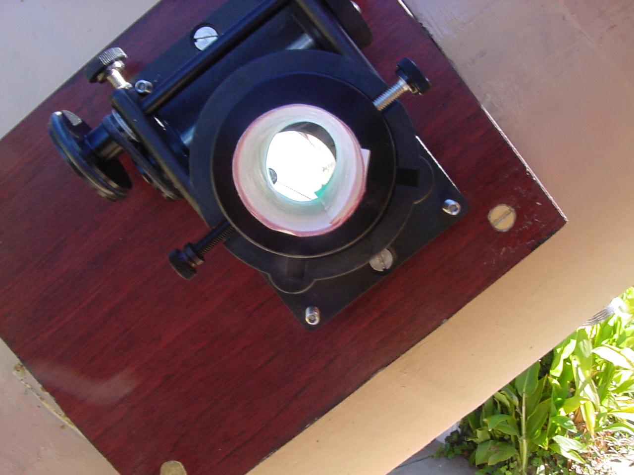
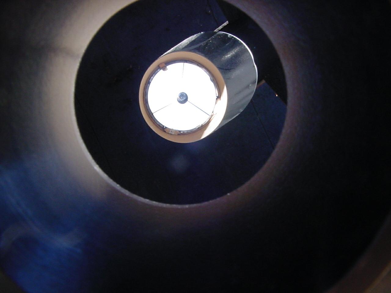
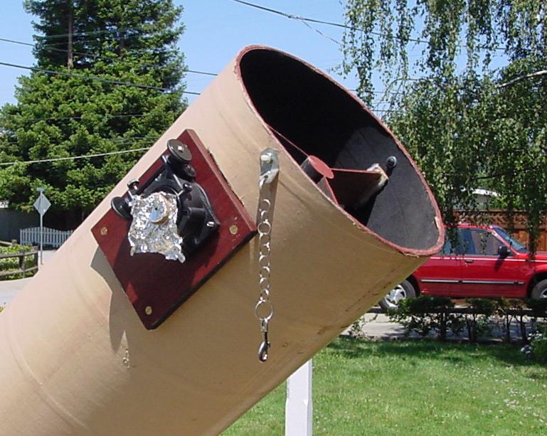
As we begin the diagonal is not in front of the eyepiece and the mirror is tipped. If the telescope had been in adjustment before we would tip the telescope up and tap it on the bottom to seat the mirror on the mirror cell. In the distance can be seen an out of focus image of our favorite power pole insulator. We have taken a sheet of printer paper and painted one edge green and the other edge red. The paper is rolled up and put through the eyepiece tube. If we position our head in the right place there is a green circle concentric inside a red circle. |
|
The spider legs were cut the same length to hold the diagonal in the center of the tube. If there is an adjustment for tilting the eyepiece tube we have tilted the eyepiece tube to point at the diagonal. When we work the focus of the eyepiece the paper should always point at the diagonal if we have a good focuser. I'm the guy with the camera. |
|
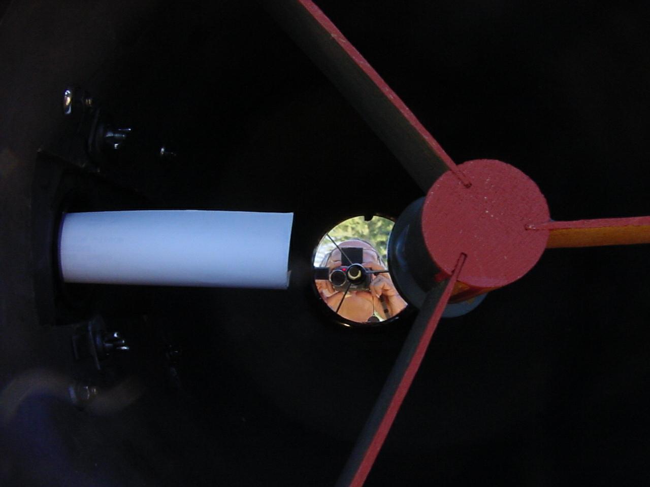
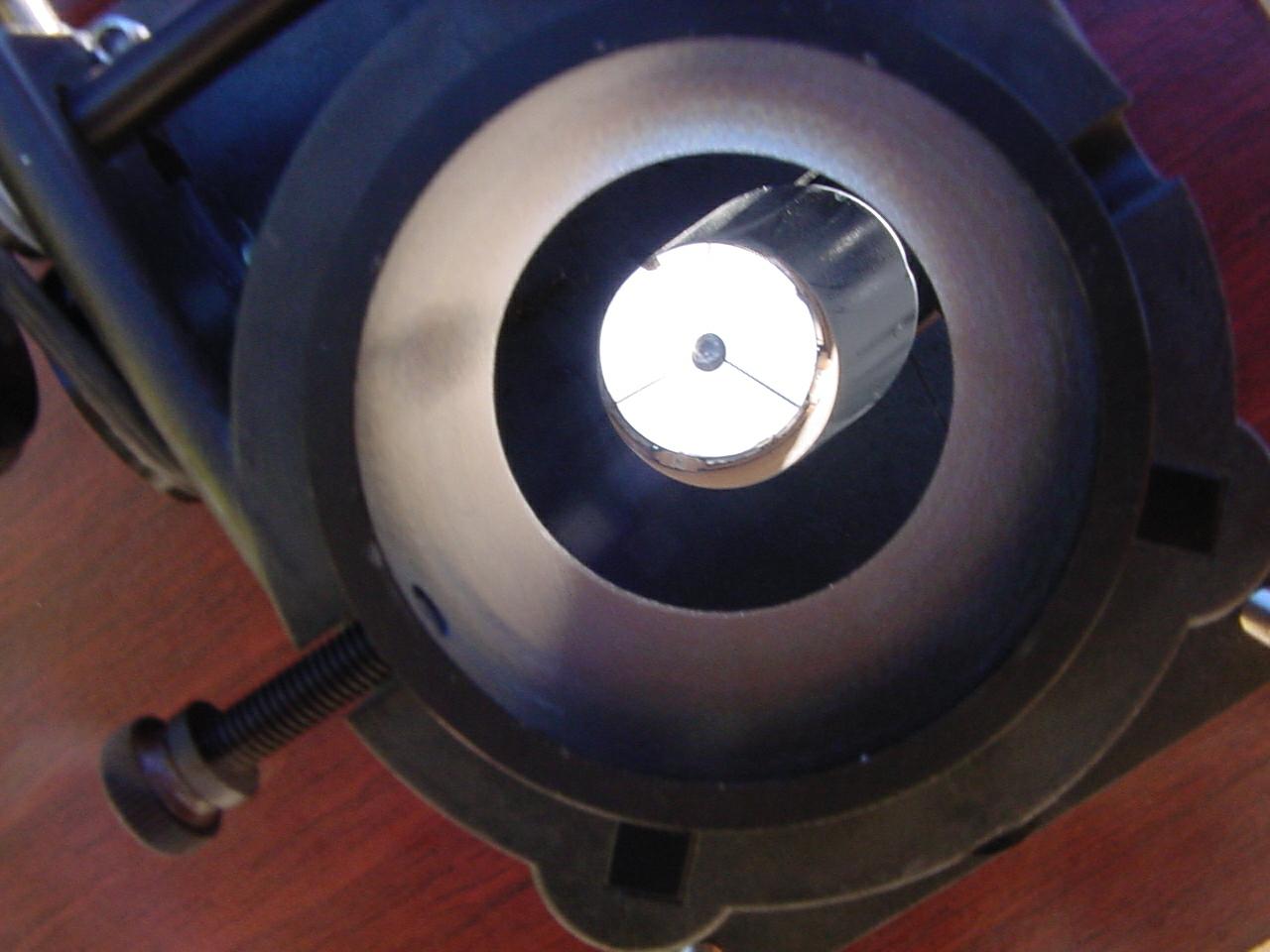
We have adjusted the spider and the mirror cell adjustments. It looks better now. We can't see the whole mirror. Is the diagonal too small? No, our camera is too far out. If you look at the center of the diagonal you can see the camera lens reflected in the diagonal, reflected in the primary and reflected in the diagonal again. |
|
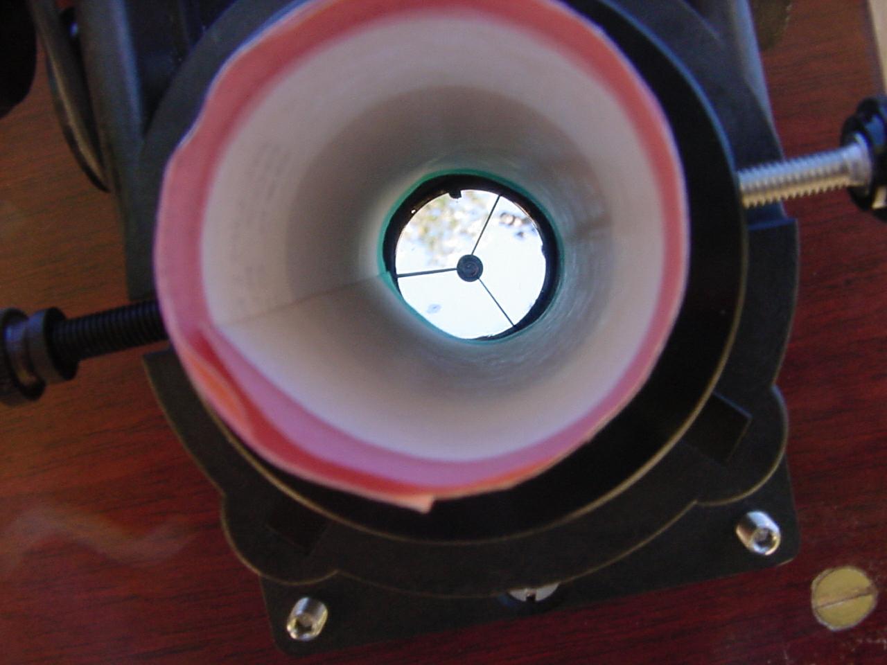
At this point the adjustments we make to collimate the telescope are to tip the diagonal north and south or east and west to center the telescope mirror inside the red and green circle. On a Dobson spider the spider is rotated in the tube for one adjustment and the spider legs slipped up and down the tube for the other adjustment. Keep in mind that since the diagonal is flat it has no optical center. The diagonal can be tipped at exactly the correct angle and not be in front of the eyepiece tube. |
|
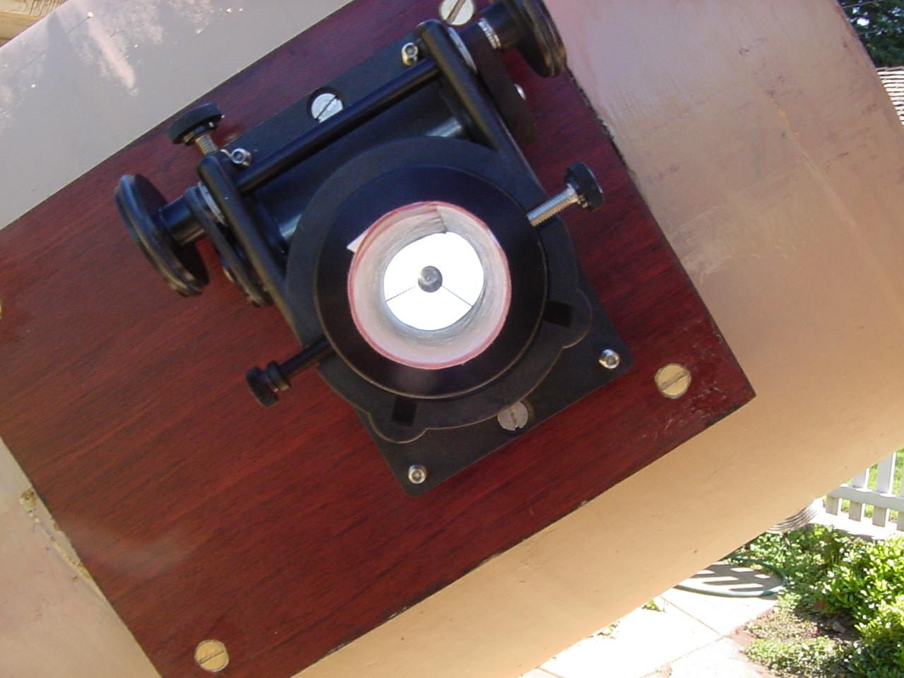
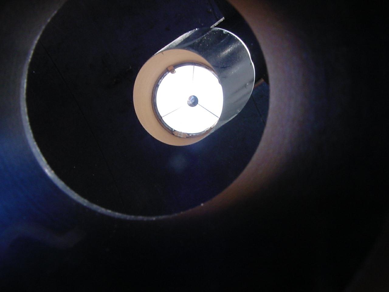
Well it looks good now. The black dot in the center is the reflection of the diagonal in the primary mirror. We adjusted the primary adjustment bolts to get the reflection of the diagonal in the center of the primary mirror. This is where we make use of the green dot. |
|
Opps, I didn't adjust anything but it looks out of adjustment again. No its OK, the problem is I'm not looking down the center of the eyepiece tube. |
|
Same problem here. |
|
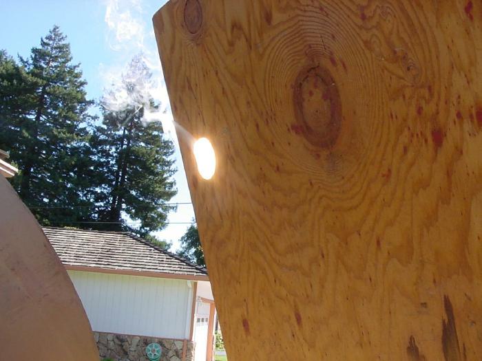
To get the good light for our picture we had the telescope pointed nearly towards the sun. This is dangerous. Since the sun is moving we pointed the telescope behind the sun. Pointing the telescope toward the sun is not required for telescope collimation. |
|
We wrap a piece of aluminum foil over the end of an eyepiece tube and poke a hole in the center of the foil to look through. We can see the primary mirror all the way to the edge. Since we bought a diagonal that is 1/4 inch oversize getting the diagonal in front of the eyepiece tube is easy. |
Collimation using the Orion laser collimator.
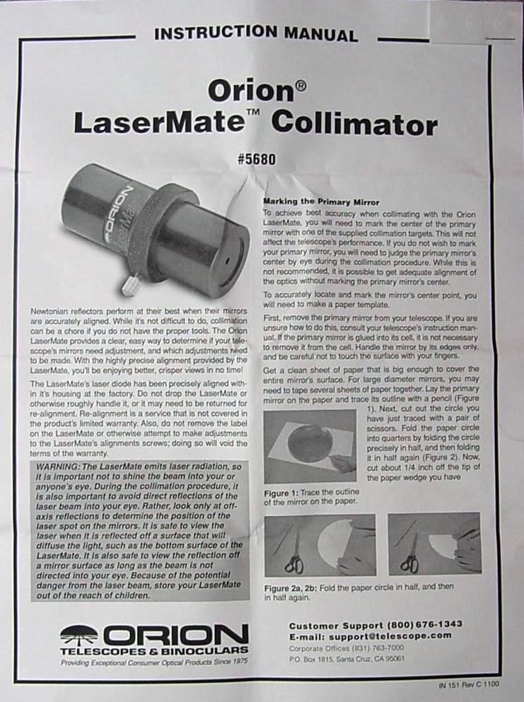 Page 1
 |
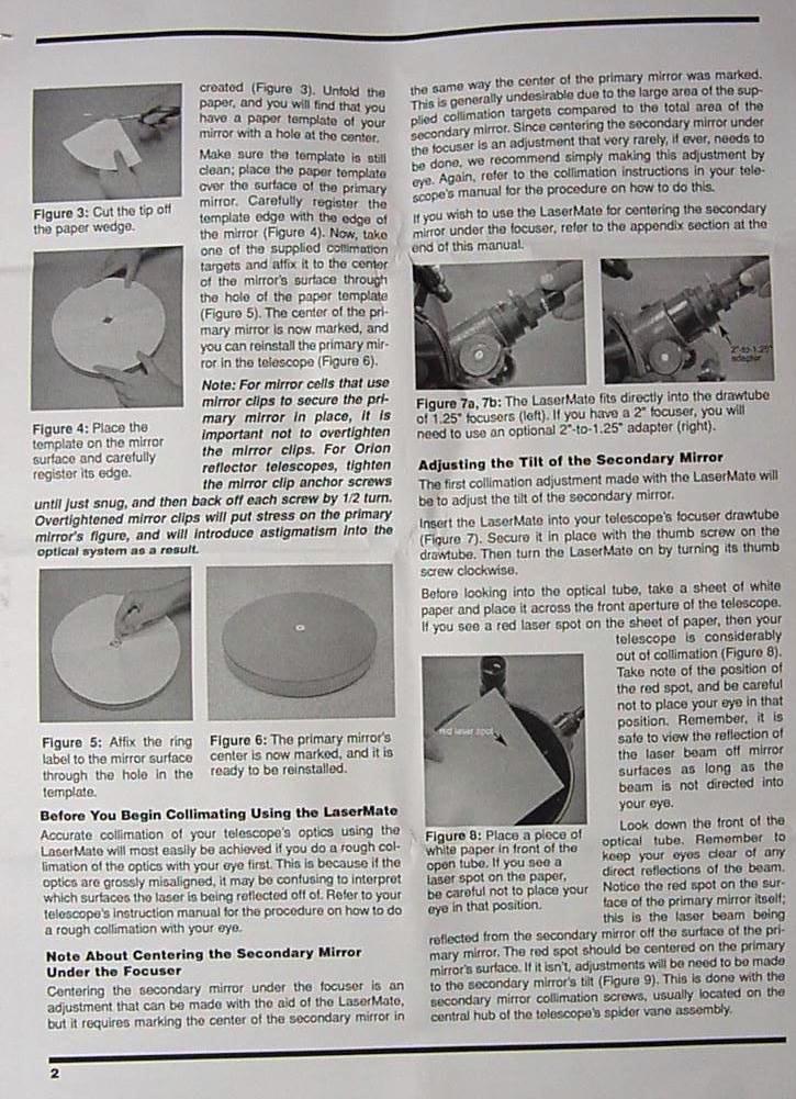 Page 2
 |
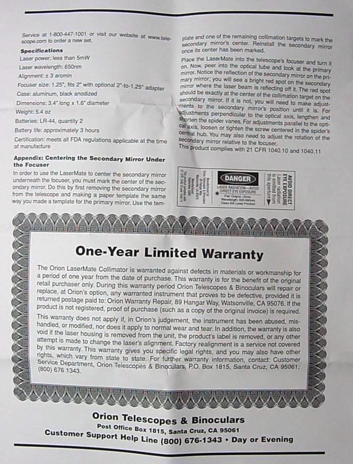
 Page 3
 |
 Page 4
 |
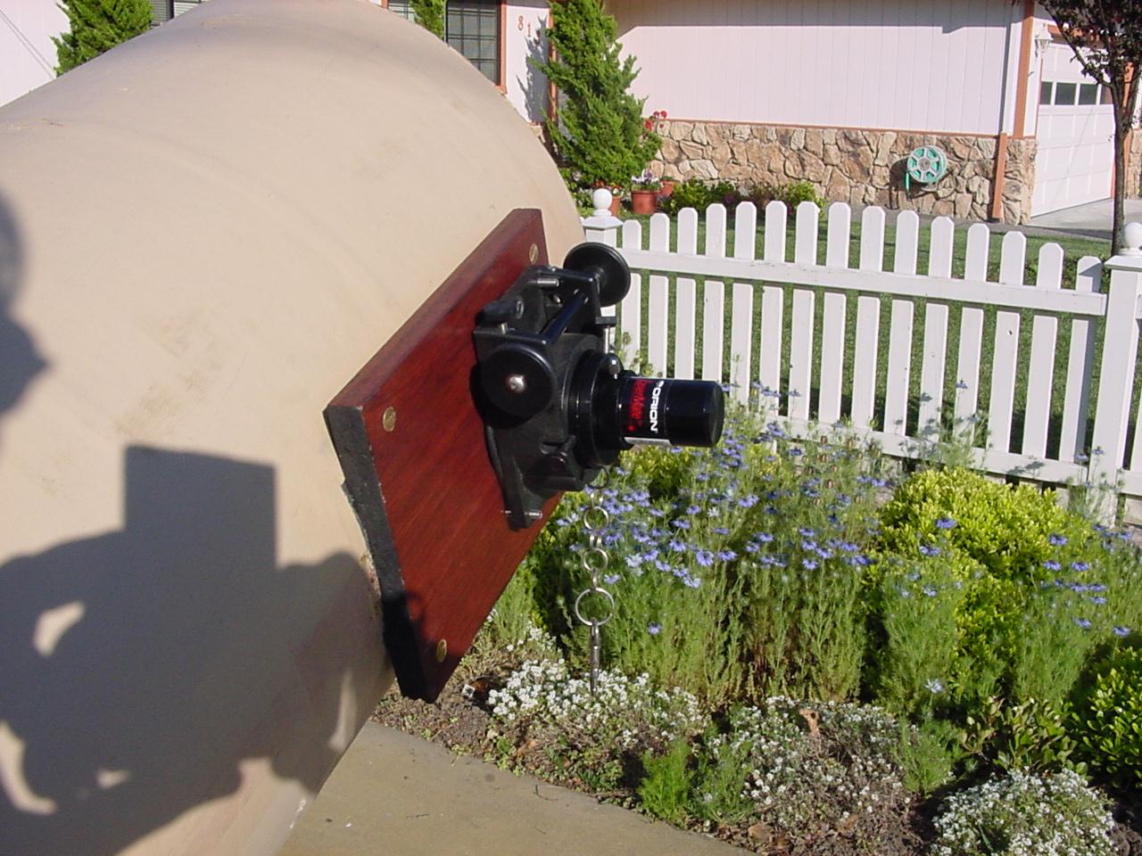 |
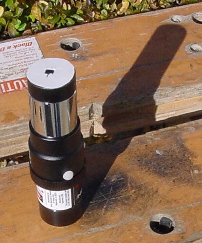
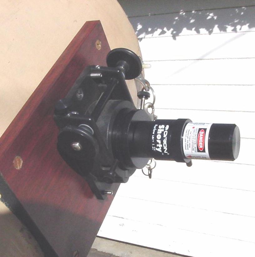
The laser collimator slips in the eyepiece tube just like an eyepiece. |
 |
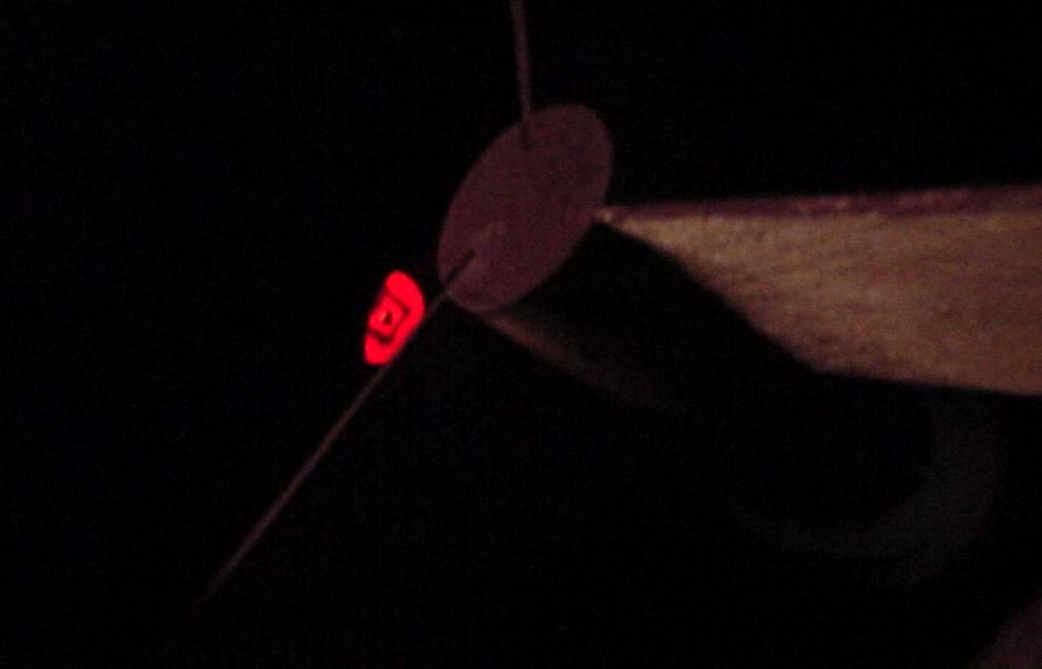
We have cut one of our green dots into strips and made a 3/8 inch square of mirror exactly in the mirror center. The laser collimator beam reflects from the diagonal and misses the center of the primary. After reflecting from the primary it misses the secondary but hits one of the spider legs. You might want to hold a piece of paper where you intend to put your eye to make sure the laser beam is not there. |
 |
We have tilted the diagonal by slipping the spider legs on the inside of the tube until the laser beam strikes the center of the mirror. |
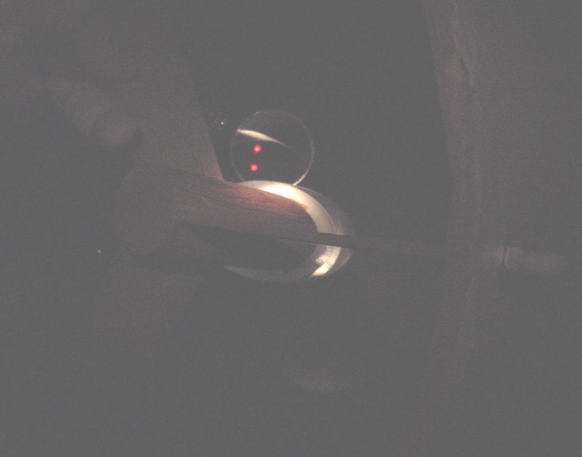 |
Next using a mechanics mirror, similar to a dental mirror, we see that there are two red dots of laser light on the face of the diagonal. We are not seeing the direct reflection of the laser. The laser light is so bright we can see light scattered from the diagonal surface. One dot is from light directly from the laser. The other dot is the light reflected from the diagonal and then from the primary mirror. |
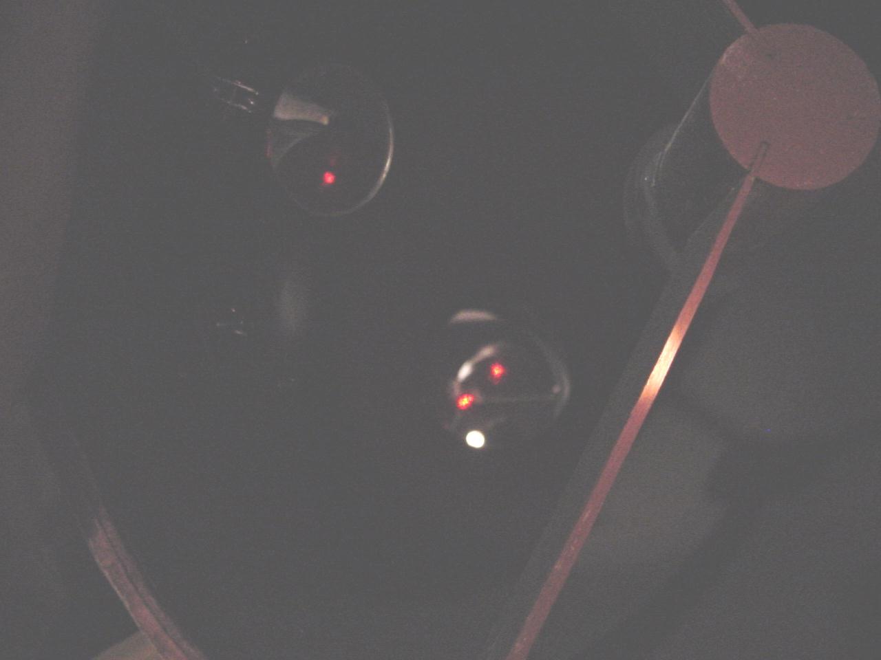 |
We adjust the primary mirror adjustment bolts until the two dots are one. |
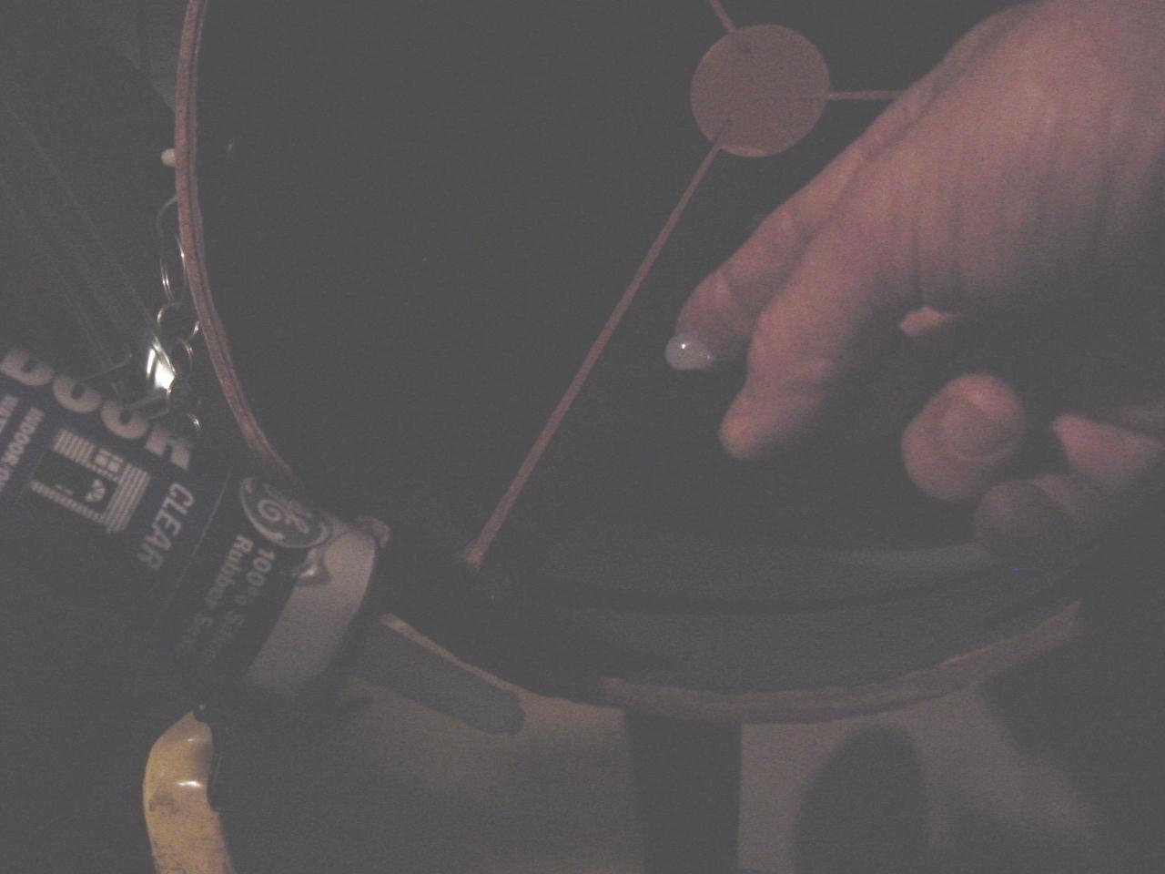 |
Then we tack the end of the spider leg to the tube with a bit of silicon sealant. If you don't use too much sealant it is easy to make further adjustments later. |
|
And of course just because the angles are correct it doesn't mean the diagonal is centered in front of the eyepiece tube. If its not right slip the spider legs in the tube and then recheck with the laser collimator. |
There is another type of laser collimator used to collimate Cassegrain telescopes. It is called a holographic laser collimator.
We found the article 'Collimation with a Barlowed Laser' in the January, 2003 issue of Sky and Telescope, page 120. We had noted that after collimation with the laser if we loosened the eyepiece set screw and wiggled the laser in the eyepiece tube the red dot on the primary mirror would jump around about 3 inches. No problem to readjust a Dobson spider but on some scopes readjusting the spider is a major project.
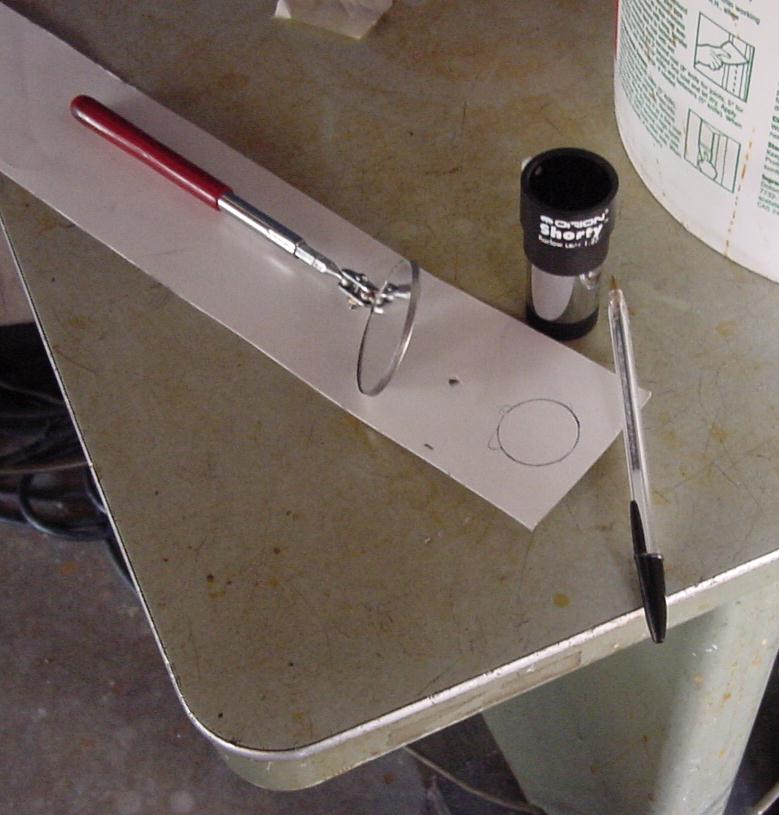 |
Since we already have a Barlow we decided to try out the setup in the Sky and Telescope article. The only extra thing required is a small screen to stick on the front of the Barlow. |
 |
After cutting out the poster board circle with scissors we mark the center and cut a small hole with a utility knife to let the laser beam pass. We cut three small squares of double stick rug tape to stick the screen to the Barlow. |
 |
Now instead of a small spot on the mirror there is a lighted area about the size of a tennis ball. And now even if the lighted area is not centered on the primary center the primary's center is still illuminated. |
 |
Looking at the screen on the Barlow we see the silhouette of the marking pen square we are now using to mark the mirror center. We adjusted the tailgate bolts ever so slightly to move the silhouette to center on the screen. The author of the article says this small adjustment can be important on low F number telescopes. |