You can make a good telescope mirror without a mirror tester. If you are working from a small apartment with no place to store tools and materials then best to skip the tester and test on some type of artificial star. At the other extreme if you plan to conduct telescope making classes over a period of time then a tester would be very useful. Obviously one tester can test many mirrors.
I needed a tester to do final testing on the Ronchi / Foucault Java Applet, otherwise I would have traveled to Chabot Space and Science Center for mirror testing or just used the good artificial star I already have.
I set requirements for my tester. I wanted something as good as the tester described in the Sky and Telescope article and I wanted to use all new, low tech, materials. If you are a machinist undoubtedly you can make something better for less money.
 |
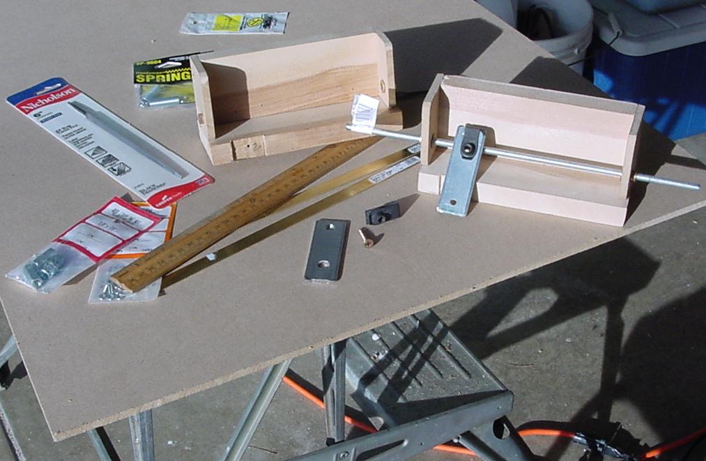
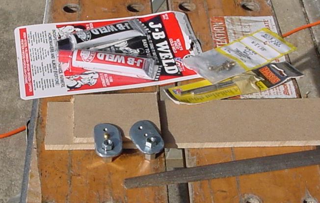
Here are our parts. We didn't take them out of the bar code wrappers because we knew some of them would not be used. The only 'high tech' parts we got for free were the traffic signal LED's. |
Quantities below based on building one tester. Some parts such as the pressed board required buying ten times more than we actually used.
| Quan | Part number | Description | Price, Dec. 2002 |
| 1 | 30513 | Ronchi Ruling, 1" SQ, 100 LPI, Edmunds Industrial Optics | 14.20 |
| 1 | 32333 | Prism, RA, 15mm, AL coated, TS, Edmunds Industrial Optics | 29.00 |
| 1 | 629377 | Maple 1X4, Home Depot | 5.52 |
| 1 | 718793328125 | 2' X 4', 1/4" Pressed hardboard, Home Depot | 3.44 |
| 1 | 044074429558 | Brass Hinge Set, Home Depot | 2.38 |
| 1 | Short length of 1/2' copper pipe, solder type of pipe | 1.89 | |
| 2 | 030699170005 | 1/4-20 Threaded Rod @.69, Home Depot | 1.38 |
| 1 | 030699191161 | Threaded rod coupling, Home Depot | .72 |
| 6 | Various screws, etc., @$.78, Home Depot | 4.68 | |
| 1 | 043425826558 | J B Weld, Home Depot | 3.97 |
| 1 | 049793096043 | Extension Spring, Home Depot | 1.92 |
| 1 | 030699544745 | Insert Nuts ( for tripod screw ), Home Depot | 2.20 |
| 1 | 030699655280 | Rubber covered clamp, CLAMPLOOM3, Home Depot | .56 |
| 4 | Various twist drills @$3.25, Home Depot | 13.00 | |
| 1 | Can of Shellac, Home Depot | 4.97 | |
| 1 | 040395512030 | Steel Shapes, Flat ( 1 X 1/8 ? ), Orchard Supply | 2.89 |
| 1 | 040395851245 | Brass Flats, ( 1.2 X .032 ), Orchard Supply | 1.29 |
| 1 | 008236069723 | Box of 1/4 - 20 Hex Nuts, Orchard Supply | 2.89 |
| 1 | 1/4 SAE Washers, Orchard Supply | .49 | |
| Various Hardware, clip nuts, knobs, bronze bushings, OSH | 12.00 | ||
| 1 | 038594000014 | Extension Spring, Orchard Supply | 2.49 |
| 1 | 038594005668 | Compression Spring, Orchard Supply | 2.49 |
| 10 | 6493894 | Speaker Wire @$.12, Orchard Supply | 1.20 |
| 3 | 7760127 | Speaker Wire @$.06, Orchard Supply | .18 |
| 1 | 032076140786 | Alligator Clip 2PK, Orchard Supply | .99 |
| 1 | 150 OHM 3W Pot, variable resistor for dimming | 3.99 | |
| 1 | 2760147 | PC BOARD, Radio Shack | 3.99 |
| 3 | 1/2 watt, axial lead fixed resistors @ 1.30, (Electronics Store) | 3.90 | |
| 1 | Mini Toggle Switch (Optional) | 4.25 | |
| 1 | Quick-Conn, Spade lugs, male and female | 2.00 | |
| 1 | 3/8 inch heat shrink tubing, black | 2.00 | |
| 1 | X235 | X-ACTO Medium Saw Blade,( to saw PC board ), hobby store | 3.05 |
| Total approximately | $140 |
We have a few carpenters tools, saw, etc. plus an electric drill motor and a bench grinder.
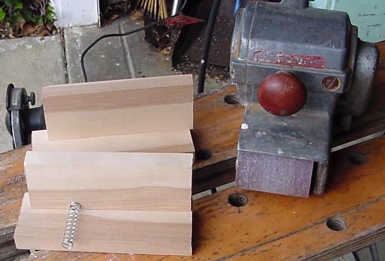 |
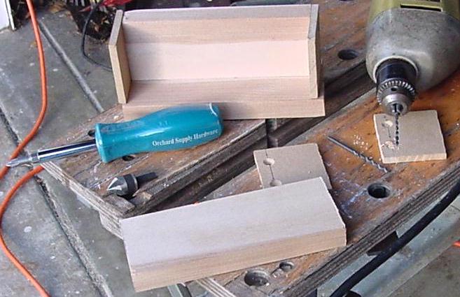
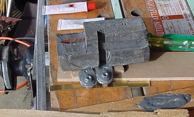
This is one of those 'design as you build' projects. Since it will require only about 20 percent more effort to build two testers we decide to build two. We cut these blocks with a hand saw. If we had a miter box we wouldn't have had to square them up with the belt sander. One block is seven inches long the other is shorter by twice the thickness of the pressed board. |
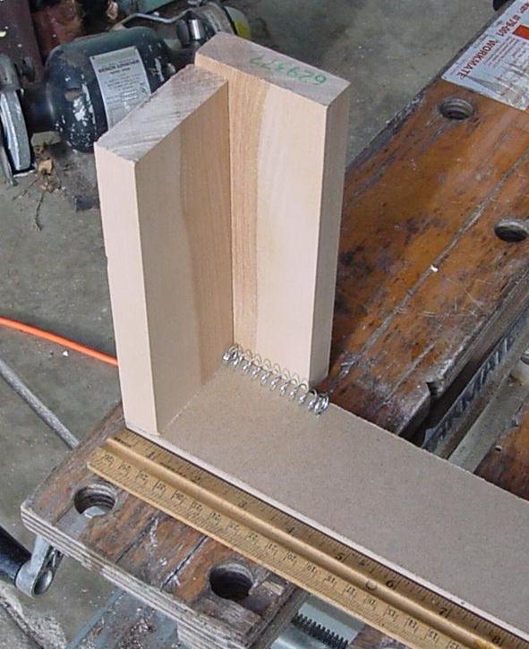 |
After cutting a strip from the pressed board we check the fit. |
 |
Here we pre drill the pressed board and the shorter block for some 1 1/4 inch deck screws. Then counter sink the pressed board for the screw heads. |
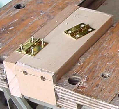 |
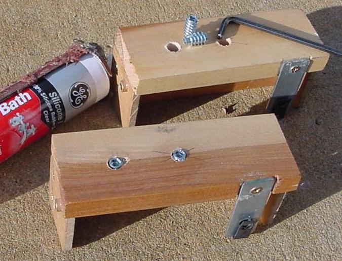
The brass screws that came with the brass hinges turned out to be very easy to twist off even after pre drilling the maple with a small drill. We went back and bought small stainless screws. Later we loosened the screws and put silicon seal between to keep the hinges from slipping on the wood. |
 |
We drilled the holes for the bronze bushings and glued
the bushings to the pressed board with the treaded rod installed to hold
the bushings straight while the glue dried. The bushing flange is on the
inside. We cut some of the flat steel bar and put masking tape on it so
we could carefully lay out the holes for the clip nuts. The clip nut
hole is slightly low so we notch the top of the steel to keep the clip
nut from rotating. Careful work with the bench grinder helps. We saw the
edges of the slot in the wood with a hacksaw and carefully chisel out
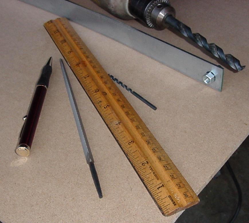
between the cuts. Hints on drilling: Mark the center of the hole with a center punch. This keeps the drill from 'wandering'. Drill a small 3/32" hole first. When the large drill breaks through the steel the steel will spin around like the blade on a lawn mower so be careful. Sometimes it helps to drill part way from both sides. Use a drill press and vise if you have them. We finish the day by sealing the wood and pressed board with a coat of clear polyurethane. |
 |
After cutting the brass 'slide' the proper length using the grinder we make a slot in the press board at each end using the 3/32 inch drill repeatedly. After trimming the slide hole with a pocket knife we mark the position of the knife edge traverse screw hole. |
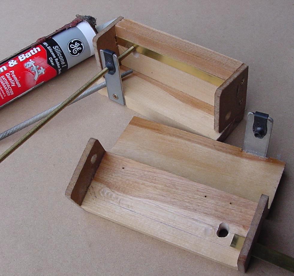 |
Next we drill the hole and after a bit of careful grinding and file work glue the brass slide in place with silicon seal. |
 |
We put it aside until the next day to let the glue cure. |
 |
There is more steel flat remaining and here we drill an undersize hole and file it so the treaded rod coupling will just slip through. |
 |
After some sawing and careful grinding and testing on the threaded rod and more grinding the slide followers are ready to be glued. We have drilled and taped two holes through the slide followers. One to anchor the circuit board and the other to anchor the J B Weld. We clean the slide followers in paint thinner and then heat them a bit to drive off the solvent. Then prop them in the correct position. |
 |
We mix the J B Weld on a shingle and apply carefully. Then leave it to cure over night. |
 |
Next we install the 1/4 - 20 Insert Nuts. You need to use a 3/8 drill to make the hole big enough otherwise the Allen wrench will strip when you install them. Careful when drilling, the drill grabs in the maple. Lube the nuts with silicon sealant. Then after installation grind the nuts flush with the grinder. |
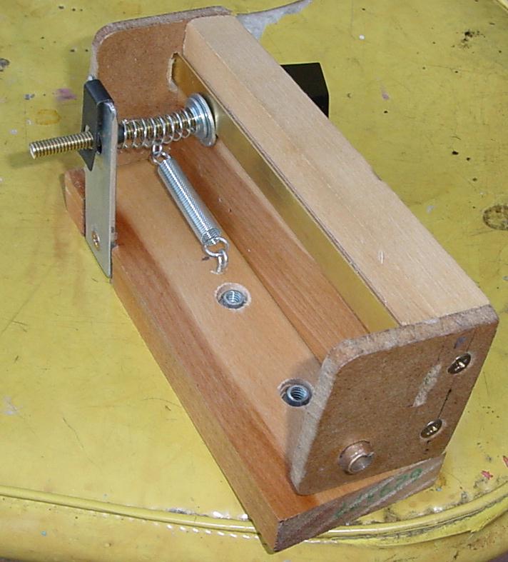 |
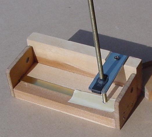
In this picture we have assembled the traverse drive with its tensioner spring. And also installed a tensioner spring to keep the hinges from sliding lengthwise. The hinges have about .004 inch play without the spring tension. |
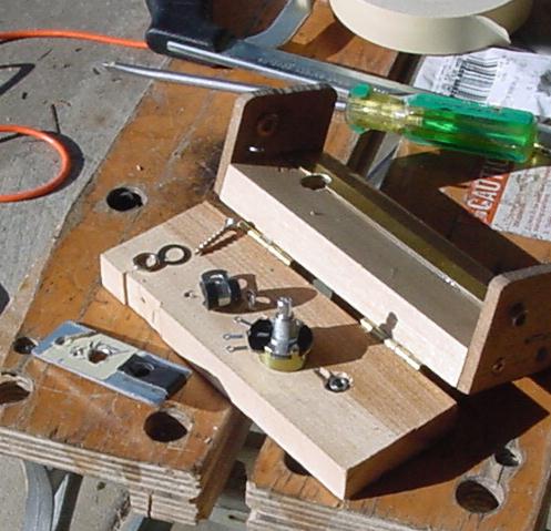 |
We found a good place to install the dimmer pot on the steel plate. More careful drilling. The pot needs to be at least 150 ohms. 300 ohms would probably be better. The strain relief clamp is also installed. |
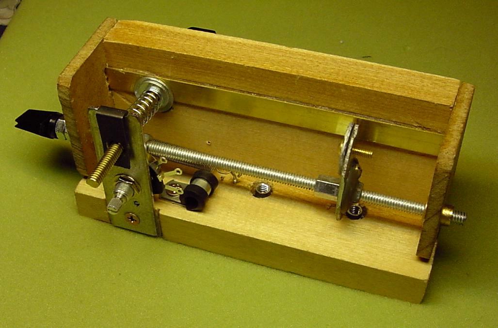 |
Here we test the 'Z' axis drive. There is a third tensioner spring hidden behind the traverse drive to keep the treaded rod from sliding in the bronze bushings. A bit of clear silicon vacuum grease and everything works smoothly. |
 |
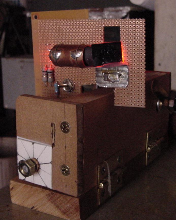
We have worked on the PC board with the X-ACTO saw. It is now slotted on the bottom for the thread coupling and mounts on the slide follower with a screw and washer. To make the assembly more stiff we doubled the PC board and to tension the thread coupling we added the rubber bands. To shade the light from the LED we sawed a segment out of the copper tube then mounted it on the circuit board with tined wire. We have installed the fixed series resistors for the LED. We found the circuit board rocked slightly when the threaded rod is rotated because we had bent the rod slightly when tightening the stop nuts for the tensioner spring but we were able to straighten the rod. |
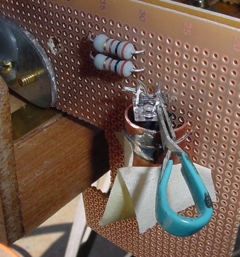 |
To protect the LED when we solder it to the tined wire we use a heat sink. Let the soldering iron get quite hot then wipe it with a damp paper towel. Then add clean solder before soldering. And work quickly. If you do a lot of fine soldering a small fan will keep the rosin smoke from your sinuses. The LED is held in position for soldering with the 3/8 shrink tube and masking tape. After soldering we can adjust the LED angle slightly by bending the tinned wire. The LED requires at least 50 ohms of resistance to drop the voltage of the 6 volt battery. In addition we add in series the 150 ohm pot and a 150 ohm fixed resistor. The switch can short out the 150 ohm fixed resistor and the pot is adjustable. |
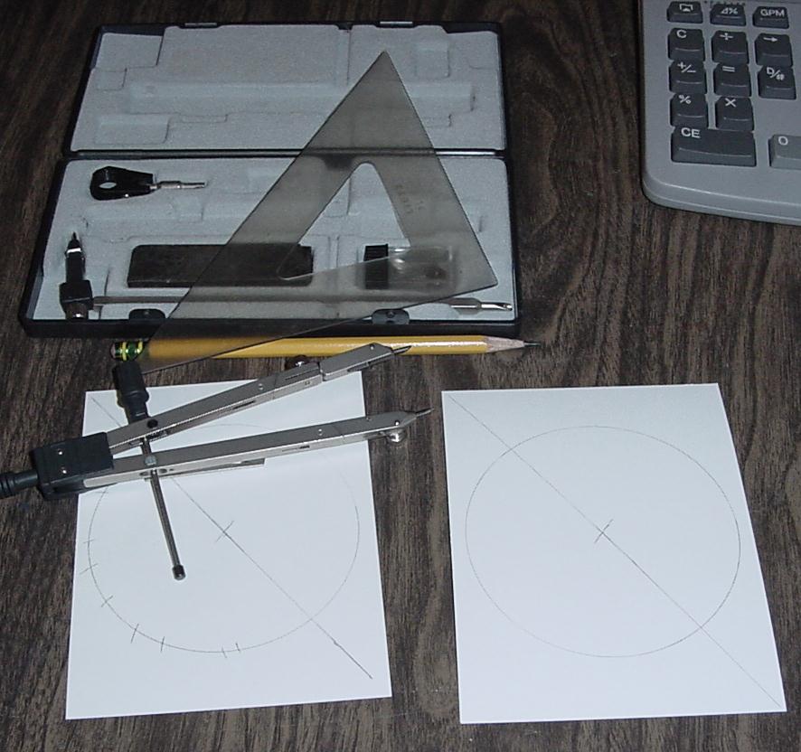 |
Here we are laying out the indicator card to go under the pointer. The 20 threads per inch rod moves 50 thousandths of an inch per turn so we want five heavy lines for 10 thousandths and five light lines for 5 thousandths. We draw a circle and work around it with the dividers until we have the ten equal divisions. After gluing it to the pressed board with sealant we spray it with shellac. The pointer is a bit of 14 gage copper wire soldered to a brass 1/4 - 20 nut and sprayed flat black and glued to the end of the threaded rod. |
 |
We frosted one face of the prism by grinding it lightly on flat glass using 5 micron AlO
abrasive. Grind wet and be sure there is no larger abrasive. The frosted
prism face will be nearest
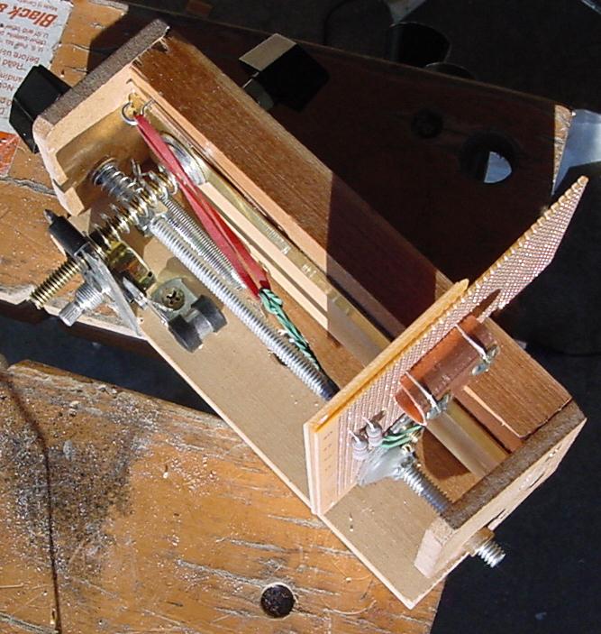
the LED. We have recycled some tinned sheet metal from a soup can to make a platform for the prism and the grating or knife edge. We drilled it with a 1/16 inch drill to match the holes in the circuit board and wired it to the circuit board with tinned wire. If you look carefully you can see a bit of uncured silicon sealant at the back of the prism. We had set up the mirror and tested everything before gluing. See below. |
 |
We set up the telescope mirror and focused the light from the tester back onto the tester circuit board. Then we covered the mirror with a sheet of white paper in order to adjust the azimuth of the prism. The light from the prism spreads in a 25 degree or so cone. We add a bit of sealant to glue the prism then push it with a screwdriver tip to make the final adjustment. Then leave it sit to cure. |
 |
A small spring will hold either the knife edge or the
grating. When the grating is used the etched grating lines face the
mirror. The knife edge was made by grinding a utility knife blade on
the bench grinder. Careful! If the grating is not inserted completely
under the spring it tends to pop out. We added some electrical tape to
increase the friction.
The brass flat you see under the traverse knob makes fine adjustments of the knife edge easier. Turning the 1/4 - 20 thread about 5 degrees is a big adjustment for the knife edge. To the left of the tester you can see the bracket for the camera. |
 |
Using the tester. |
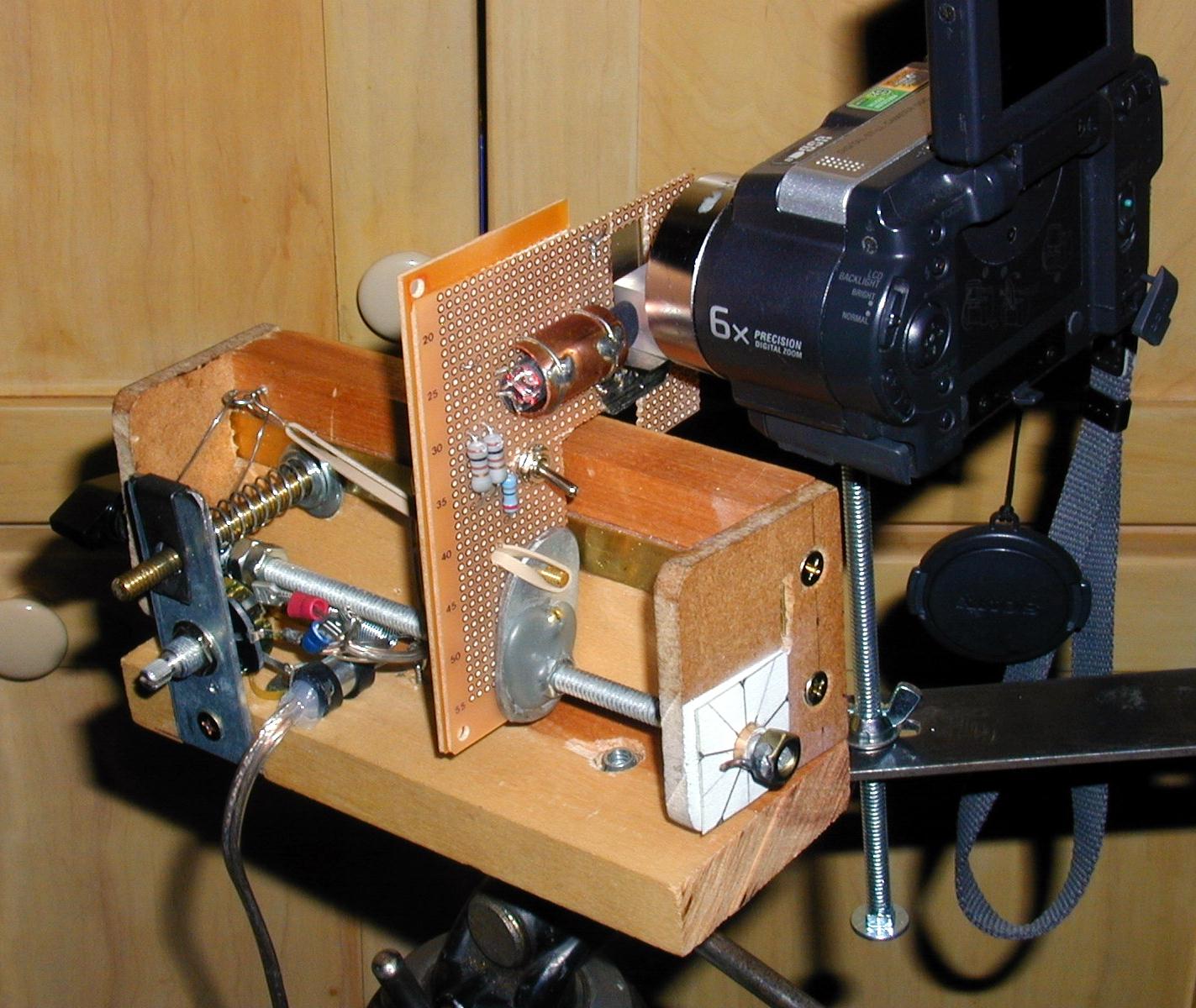 |
If you think setting up the mirror to test with the knife edge was a chore then you won't like the addition of the camera. If the camera iris is too small or improperly positioned the edge of the iris will act as a second knife edge making things quite confusing. With enough patience it can be done though it is still more of art than science. |
 |
At the focal point of the mirror center.
Moving the knife edge in from left to right the center darkens almost instantly while the shadow just creeps across at the edge. Imagine that a light source is on the right illuminating the mirror grazingly. The mirror center seems to be the flat top of a round hill. The radius of the mirror center we call Ro . |
 |
At the focal ring of the seventy percent zone.
Because of the effect of the caustic curve when testing a paraboloid at its radius of curvature all zones other than the mirror center have a focal ring rather than a focal point. We have marked the mirror center and the seventy percent zone with a marking pin. The knife edge is on the left as is the shadow at the edge showing that we are closer to the mirror than the focal ring of the mirror edge. I suspect the slight zones on the mirror in this picture are about 1/8 wave. |
 |
At the focal ring of the mirror edge.
Moving the knife edge in slowly causes the shadow to move around the edge almost instantly. At the mirror center the shadow creeps across slowly. The imaginary grazing light source is still on the right showing a plane at the mirror edge with deepening toward the mirror center. |
 |
In this picture the Ronchi grating is far enough inside the focus of the mirror center to produce five dark bars. This is the usual position for testing with the Ronchi grating. Another test using the Ronchi grating places the grating outside of focus to test for turned edge. |
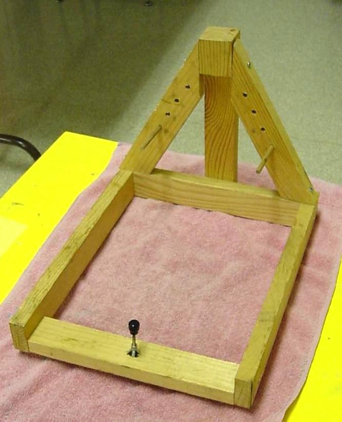 |
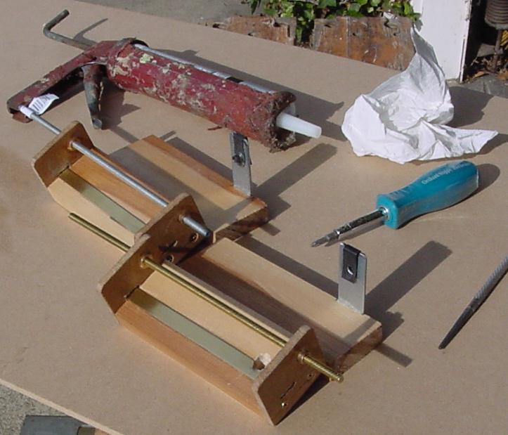
Here is a mirror test stand made by Dwight Elvey for the San Jose Astronomical Association telescope making group. |
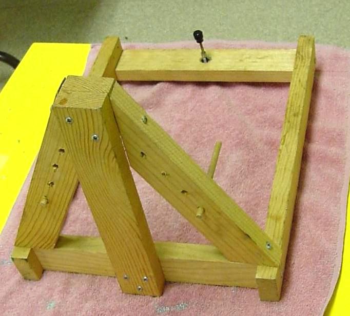 |
If you don't have a test stand you can test the mirror in the telescope with the diagonal and spider removed. |