Some Basic Optics
Spherical Aberration
Testing Amateur Telescope Mirrors
Distance Between the Radii of Curvature of a Paraboloid being tested at its Radius of Curvature
Perceptual Aid in Understanding the Foucault Test
Ronchi Test at the Radius of Curvature
How Well Must a Mirror Be Corrected?
More Mirror Testing Methods
Reading the Curve of the Mirror with an Eyepiece
Using Mirror Edge Diffraction while Mirror Testing
Summary
For Those Who Want More Information About Mirror Testing
The Caustic Test
The DAFT Test
The Null Lens
Strehl Ratio
Professional Mirror Testing
Foot Note
References
Some Basic Optics
A dish shaped mirror, concave mirror, has some properties that are the same as a magnifying lens. A concave mirror will concentrate the sun's beams to burn paper. When we want to make a telescope to look at the night time stars we often make ourselves a mirror instead of a lens. If the light reflects from the mirror without passing through the glass we need not worry about the curve on the back surface of the mirror glass. Imagine ourselves at the center of a giant hollow ball, lets say we are at the center of a giant silver Christmas tree ball. We hold in our hand a lighted flashlight bulb. Light from the bulb reflects from the inside of the ball and returns directly to the bulb. Now we take a big cookie cutter and cut a round hole in the giant ball. The circular piece we cut out will be our telescope mirror. If we move our light a tad to the left, the returning reflected light will move a tad to the right.
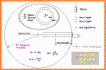 If
we place our eye in the path of the returning light, all of the light that reflected from the
mirror will enter our eye. We will perceive that the entire surface of the mirror is glowing with the same brightness. The light
rays returning
from the mirror are in the shape of a cone. The point of the cone is a point on a surface known as the image
field. If there is nothing in the image field to stop the light, all the light rays will penetrate and exit the image field to
form another cone of spreading rays. If our eye is close enough to the image field the exiting cone of light will be
small enough to fit through the pupil of our eye. Otherwise if our eye is further from the mirror only a portion of the
mirror will appear to be glowing.
Early telescope makers found that a spherical mirror would not focus the light from a star to a point. Amateur astronomers call this effect spherical aberration. The parallel rays or collimated beam from the star will focus at an image field half way between the center of the sphere and the surface of the sphere. Light rays from the edge of the mirror form an image field slightly closer to the mirror than rays from the center of the mirror. As a result the telescope will not produce clear images. The curve that is required for the mirror is a parabola or in three dimensional terms a paraboloid.
Testing Amateur Telescope Mirrors
It has become common practice for telescope makers such as John Dobson to polish the telescope mirror until an image can be formed, then build the telescope tube and base to the proper length. (See book and video by John Dobson.) The mirror curve is then tested using the collimated beam produced by the suns refection from a distant power pole insulator. CAUTION, Never point the telescope toward the sun. Using an eyepiece of the proper focal length and some considerable skill by the telescope maker the figure of the mirror can be determined quickly. Many telescope makers prefer to test mirrors in the shop. If you have professional test equipment to generate a collimated beam of light there is no problem. The rest of us often use the Foucault test to test the mirror at its radii rather than at its focus. Measuring the distance between the foci of the zones of the mirror at its radius of curvature may be done by various methods. Using one possible method, a piece of old band saw blade is made to press a razor blade against the screw of a micrometer. A washer is glued to the band saw blade to keep it centered on the micrometer shaft and a paper clip holds the razor blade to the assembly. In this way the difference between the radii of curvature of different zones of the mirror can be compared. Using this method the mirror is often first polished to a spherical curve then "corrected" to the desired parabolic curve. Making the sphere is relatively easy since two curved surfaces of revolution tend to become spherical when polished against each other. After the spherical mirror is polished then either a parabolizing stroke with a full size lap or an under size lap may be used to "parabolize" or "correct" the mirror. The mirror may be "parabolized" by shortening the radius of curvature of the center of the mirror. As the mirror is corrected the radius of curvature of the center of the mirror becomes shorter. If the proper polishing strokes are used the radius of curvature of the zone 7/10 of the distance from the center of the mirror to its edge will have a radius of curvature 1/2 way between the radius of curvature of the center and the radius of curvature of the edge.
Distance Between the Radii of Curvature of a Paraboloid being tested at its Center of Curvature.
 Using the radius of curvature of the center of the
mirror as the zero reference point on the micrometer
scale.
70% zone = (radius of mirror) x (radius of mirror)
divided by ( (Radius of curvature) x 2 )
edge zone = (radius of mirror) x (radius of mirror)
divided by Radius of curvature
So for a 12 inch telescope mirror with a 60 inch focal length the difference between center and edge foci would be:
6 x 6 / 120 = 36 / 120 = .3 = three hundred thousandths of an inch.
Note: Using this formula while testing the light
remains stationary while the knife edge or grating moves toward or away from
the mirror.
If the light source moves with the knife edge then we must move the
light source and knife edge together half as far to see the same result.
To find the 70% zone while testing the mirror it is useful to place a small stick in front of the mirror and place sewing pins in the stick at the center, the 70% zone and the edge. The pins at the 70% zone would be 4.2 inches from the center of the mirror in our example. With the light source stationary move the knife edge .150 away from the mirror to move from the focus of the mirror center to the focus of the 70% zone and another .150 to reach the focus of the mirror edge or a total of .300 in this example. To better understand the Foucault test view the graphic with the formula below left and the animated graphics below right.
There are variations of the r sq / 2R formula for different situations.
Perceptual Aid in Understanding the Foucault Test
Besides measuring the radii of curvature of the mirror the Foucault
test can also be used to find zones of
improper curve on the mirror. Sometimes during the polishing of the
mirror a 'zone' or a turned down edge will be generated due to an
improper polishing lap, incorrect polishing strokes or temperature
variations in the glass. As an experiment we can wrap a tissue around our
finger and hold our finger against the mirror as it sits on the test stand. Returning to the knife edge we observe on the
mirror something that looks like a dimple where our finger had been on the
glass. This is caused by the expansion of the glass due to the heat
from our finger.
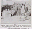
If you think of the mirror as a flat plain with a hill on the plane the rising sun might be thought of as shining on the hill from the opposite side of the plain as the knife edge is located. To see a dramatic effect place a hot cup of coffee below the mirror on the test stand.
Ronchi Test at the Radius of Curvature
 Using the Ronchi test for testing a paraboloid at its
center of curvature the zone of the mirror which comes
to a focus at the Ronchi grating will look like a Greek letter Phi. Phi is like an O with an up and down line through
it. The O part of the Phi is the zone of interest.
The Phi
pattern may be dark on light or light on
dark.
A paraboloid tested at its focus using star light will show the same Ronchi pattern as a sphere being tested at its radius of curvature. The pattern being straight black bars which grow to cover the entire mirror as the grating is moved to the image plane. When the Ronchi grating is precisely at the focus the focal point of light from the entire mirror will either fall on a grating line and be blocked or pass through the grating to your eye. Note, the Ronchi test can tell you if all the light at some hour angle on the mirror will come to a focus at the same point. The test will not tell you how the optics were set up to do this.
The curved patterns of the Ronchi test when testing a paraboloid at the center of curvature are easier to understand if the Ronchi grating is placed somewhat inside of the radius of curvature. Move the grating towards the mirror from the focus at the radius of curvature until five dark up and down bars appear on the mirror with one of the dark bars across the center of the mirror. Using this Ronchi testing method alone it is possible to correct a mirror to 1/4 wave.
If the desired Ronchi pattern is obtained except for the outer 1/8 inch or so at the edge of the mirror it is usually better to mask the outer 1/8 inch and proceed with the project. This Ronchi test is one of the tests used at the Chabot Space and Science Center Telescope Makers Work Shop. We have included some Ronchi-grams taken at the center of curvature using the equipment at the Telescope Makers Workshop.
For more information about the Ronchi grating try the Ronchi page at Stellafane.
The Ronchi Program
 The Ronchi program generates the curved bars seen
while testing the parabolic mirror near the radius of curvature.
The Ronchi Program is available
in a version that will run in the web browser. The DOS
version of the Ronchi Program is in a sub folder on this disk called
DOS_STUFF.
If you need the Ronchi Program in Mac version contact the
in April 1991 on page 416.
If you like, view the graphic explaining the Ronchi Program.
The Foucault Program
The Foucault Program, is part of the Java and DOS version of the Ronchi Program.
Also in the web_tele folder in a sub-folder named files there is a Foucault Program which runs under MS-Windows. We have no background information on this program at this time except a copy of the online documentation. ( January 2004 )
How Well Must A Mirror Be Corrected?
The curve on a single mirror telescope mirror need not be much more accurate than one fourth wave length of visible light. If the F number is increased to a high enough value the difference between a sphere and a paraboloid becomes less than 1 / 4 wave. For a 6 inch Newtonian Telescope this F number is about F 11. For larger mirrors the F number required to maintain 1 / 4 wave becomes too high to be practical and a spherical curve cannot be used. For more information about this read the Tele Topics article
More Mirror Testing Methods
 Here is another plan for figuring your mirror.
Polish the mirror to the spherical stage then complete
the telescope. Then begin parabolizing, testing the mirror
in the shop using the knife edge and the micrometer.
As the correcting nears completion set up a small
bright light such as an auto stop lamp or a silver Christmas
ornament with a flashlight shining on it. The light would need to be at least the distance given by the
formula below to reduce the spherical
aberration and one would need to wait until sometime after dark for
the heat waves to dissipate. Using the Ronchi grating and the knife edge complete the figuring. The low voltage auto stop
lamp has a small filament making it more useful than a 117
volt lamp. The knife edge test will be more sensitive if the knife
edge is parallel to the image of the lamp filament. On page 47
of the March 1995 'Sky and Telescope' there is a formula which
is useful for setting up an artificial star test. To keep the
test setup from introducing more than 1/4 wave of spherical
aberration on the wave front, the artificial star must be more than:
( mirror_diameter / F_number ) squared * 30 feet from the telescope. For my 12 inch F6.5 this distance should be 103 feet or more.
If you want to use a star for the knife edge test find the brightest star in the sky and with the knife edge glued to a safety cap, rotate the safety cap until the motion of the star in the unguided telescope is almost parallel to the knife edge. Set the star at one edge of the field and without touching the telescope let the Earths rotation slowly carry the star into the knife edge. At some point as the star moves into the knife edge you will get a perfect knife edge test if the focus is adjusted so the knife edge is at the focal point of the star.
Reading the Curve of the Mirror with an Eyepiece
Moving the eyepiece inside of focus and outside of focus one can see a tiny mirror disk. If the mirror is properly corrected the light from all the zone of the mirror will focus at the same point. If the center of the mirror happens to be too deep we will see the center of the mirror too bright when we push the eyepiece in. If the center of the mirror happens to be too flat we will see the edge of the mirror too bright when we push the eyepiece in. Any portion of the mirror that bundles too much light outside of focus is too flat. Any portion of the mirror that bundles too much light inside of focus is too deep. This test is often done using the suns refection from a distant power pole insulator. For more information contact John Dobson of the Sidewalk Astronomers. There is more information about testing at the eyepiece in this program at alt_51.htm. Pictures showing eyepiece testing are at 8_inch-nf.htm.
Using Mirror Edge Diffraction while Mirror Testing
 Understanding
the diffraction ring seen while mirror testing gives the mirror maker a
quick reading of the mirror edge.
Summary
The testing methods listed above are the most common methods used by amateur telescope makers. Each can produce good results. While polishing the mirror you should begin to gather the parts for the rest of the telescope. Most of the parts needed are listed in the Building the Telescope or with the 8 inch 'Project Scope' portion of this program. Suppliers are on the supplies page. If you are working alone without help learning may take a while. The project can be easily spread over several months ( or even years ). If you have a finished and coated telescope mirror and the construction of the telescope tube has not yet been started a substitute for the mirror can be made. First have the cabinet maker make a plywood mirror the size of your mirror. Glue a small mirror to the center of the plywood disk with silicon sealant and put an adhesive dot in the center. The plywood disk might even be weighted to be the same weight as your mirror. The plywood mirror will serve as a substitute for the real mirror during construction, alignment and balancing of the telescope tube. You and the cabinet maker won't have to worry about your prized mirror laying around a dusty woodworking shop.
For Those Who Want More Information About Mirror Testing
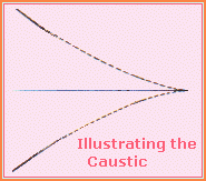
The Caustic Test
 This test is a substitute for the Foucault test.
The caustic test has nothing to do with chemicals, it
is an improvement of the Foucault test. The caustic
test would be useful for professional mirror makers. If one
studies the light rays returning from a paraboloid
which is being tested at its center of curvature one
finds that the light from a window at the center of
the mirror comes to a focus exactly on the optical
axis of the paraboloid. Now if one moves the window to
near the mirror edge the focus point becomes further
from the mirror as we expected. Something else happens.
The focus point moves off the optical axis. The loci of
foci as we move our window from the center to the edge
of the mirror disk form the 'caustic curve'. The Ronchi
program and the Foucault program on this disk do not
take this into account making their displays slightly wrong.
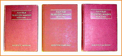
An excellent description of the caustic test including the design of test equipment is in 'Amateur Telescope Making' Book Three, Scientific American 1956. Kingsport Press, Kingsport, Tennessee. I have been told that the three Scientific American amateur telescope making books have been republished by Willmann-Bell Inc.
The DAFT Test
The Null Lens
The Surf Program
 The surf program is intended to be used with knife edge measurement made
along the mirrors 'starward' axis. Sometimes called the 'longitudinal'
axis. The program will be most useful on large, short focus mirrors
where the Ronchi test is not accurate and the artificial star test requires an
artificial star which is overly distant from the telescope. Program
features allow calculation of RMS, diagonal size, minimum distance to an artificial
star and caustic curve values.
The Surf Program is also useful for those of us that always wanted to know just how mirror errors at the eyepiece or knife edge translate into surface errors. We hear so many quotes that one mirror is 1/8 wave or 1/10 wave or even 1/100 wave but how do they really know?
RMS and Strehl Ratio
As it turns out the peak to valley errors that are usually quoted are not the best measure of wave front error at the eyepiece. The best that can be said for them is that they easily relate to things most of us can understand immediately. On Mel Bartels website and R. F. Royce website there are understandable explanations of RMS and Strehl ratio. RMS and Strehl ratio are better criteria for rating a mirror's overall performance than just one peak and one valley measurement.
It is my impression that most modern day mirror testing is done by first generating a light bundle that simulates the light of the completed system. If one were making a sphere one would test at the center of curvature or if one were making a paraboloid one would find a way to generate collimated light. There are standard test setups that can generate light with varying amounts of spherical aberration to use for component testing. The final test is best done with the system assembled. The 120 inch mirror at Lick Observatory, Mt. Hamilton, CA was tested on stars using a Draper hole screen over the aperture. The mirror was installed and removed from the telescope many times before completion.
References
A classical reference for amateur telescope mirrors is 'Amateur Telescope Making Book One' Scientific American 1953. This book is now in reprint.
If you want a background in testing telescope mirrors at the eyepiece try 'Star Testing Astronomical Telescopes' H. R. Suiter, published by Willmann-Bell, Inc. 1994.
A more technical reference is 'Astronomical Optics'
by Schroeder, Academic Press 1987.
