Grinding an Eight Inch Pyrex Mirror Blank
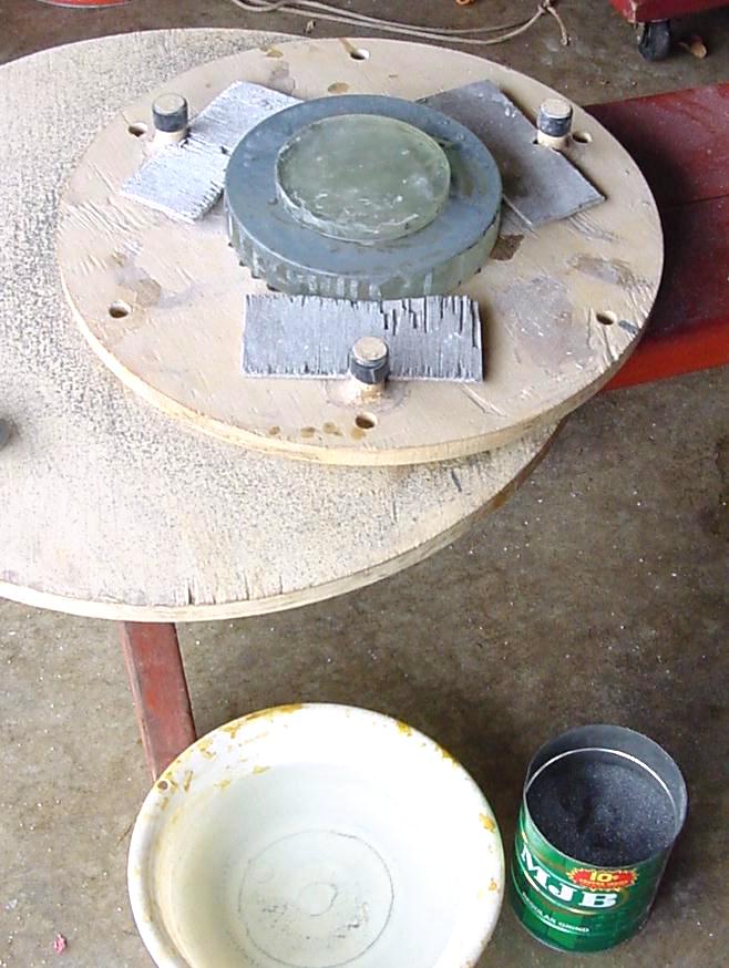 |
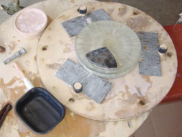
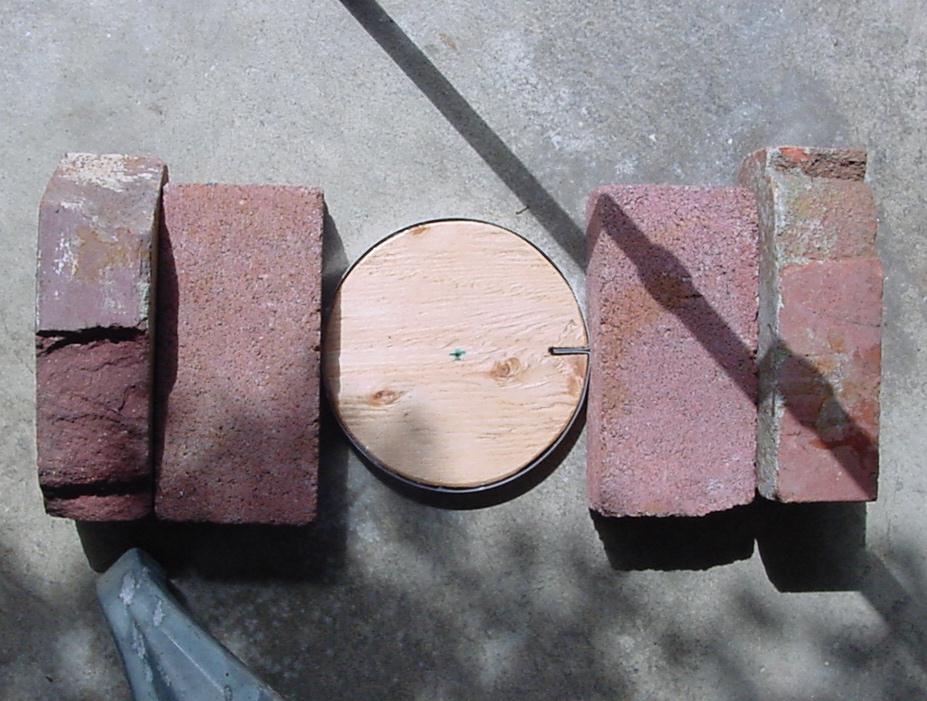
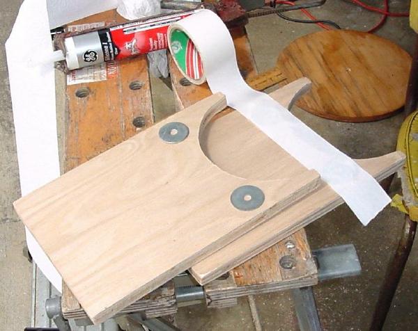
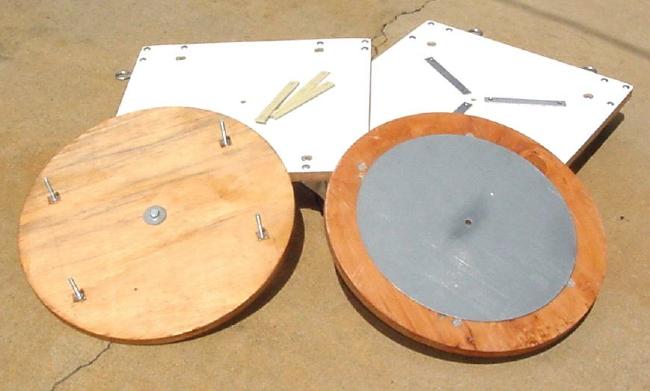
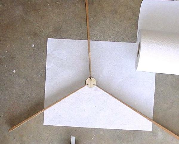
We had this nice Pyrex mirror blank that had been used as a grinding tool on a larger mirror. We modified our lazy Susan by gluing in some scrap plywood with sealant. Here we grind up 60 carborundum with a 5 inch disk of glass we had. A pipe flange or a square of scrap iron would have worked as well. Stay away from the mirror edge with this rough treatment. |
 |
When tired of grinding we sanded for a while. After about 4 hours the mirror appeared to be less than 64 inches focal length. Near the edge there was a mold mark, about 1/50 inch deep. This required another hour to work through. Try to avoid breathing the dust while grinding dry. |
 |
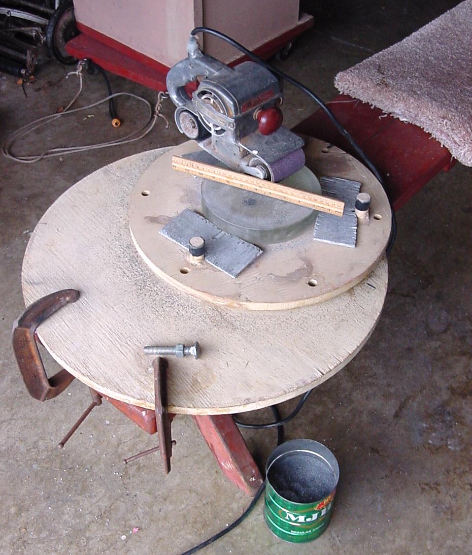
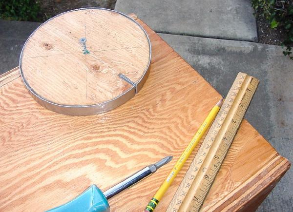
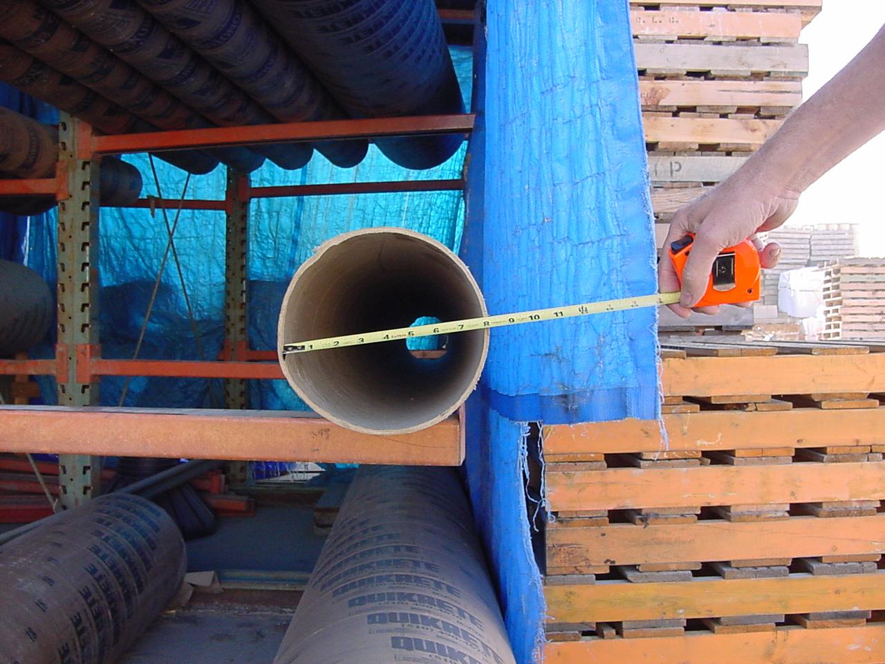
We smeared the mirror with vegetable oil to try to fill the 60 grit scratches. Careful, it's slippery. WD40 works better after the mirror is fine ground. An optical shop would probably use glycerin. Here we catch the sunlight to form a rough focus on the garage door. The ladder is used for a reference when using the tape measure. The grinding bench is tipped up to thoroughly hose off the 60 grit. We are making a long focus planetary telescope but common sense tells me not to be longer than 64 inches, F8. |
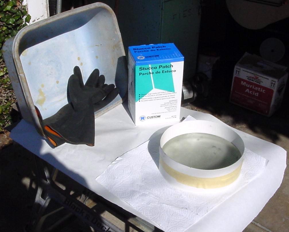 |
We will make the disk for our full size concrete tool from stucco patch. We grease the mirror with automotive bearing grease and tape a poster paper rim around the mirror. The top edge of the poster paper will determine the depth of the tool so be sure it is even. After the poster paper is well taped we smear a bit of vegetable oil on it with our finger. By molding the tool to the already pre curved mirror we will spend less time grinding away tool tiles. |
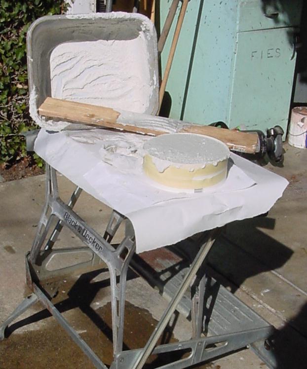 |
Un cured concrete will permanently roughen your hands so wear rubber gloves and have a pan of safety water ready. After mixing with the rubber gloves we fill the mold and scrape the extra off with a board. Don't add too much water. After about an hour we trowel the concrete with the bottom of a frozen food entree pan. If we had used mortar mix we would have had to press the mortar after 20 minutes to close the shrinkage cracks. Keep the mold in the shade so it won't bake out too fast. Time to mold tool, 4 hours including a trip to Home Depot for materials. |
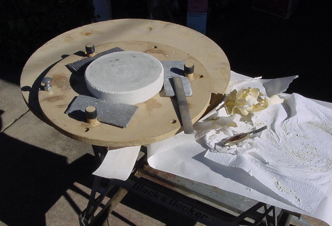 |
The next morning we strip the mold. The concrete is about as hard as plaster of Paris and we are able to bevel the edge with a rasp. We put the tool in a cool wet place to cure for two days. Now its as hard as, well, concrete. We bring the tool in the house to dry for at least four days. |
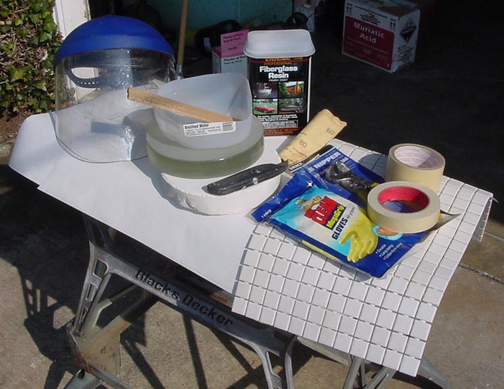 |
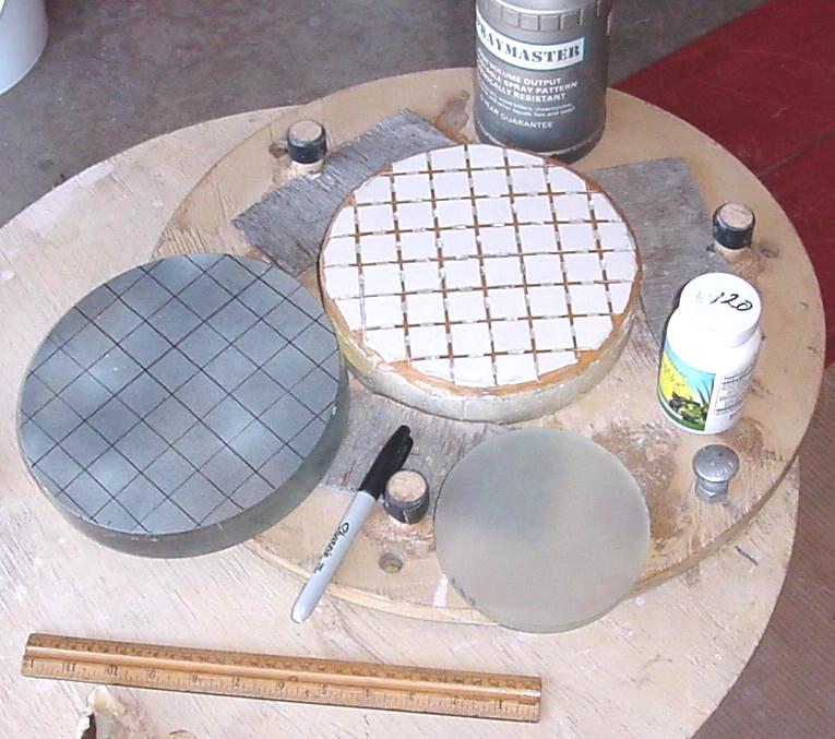
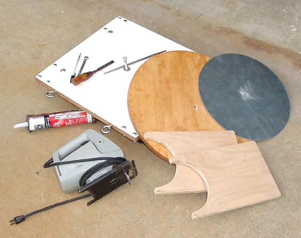
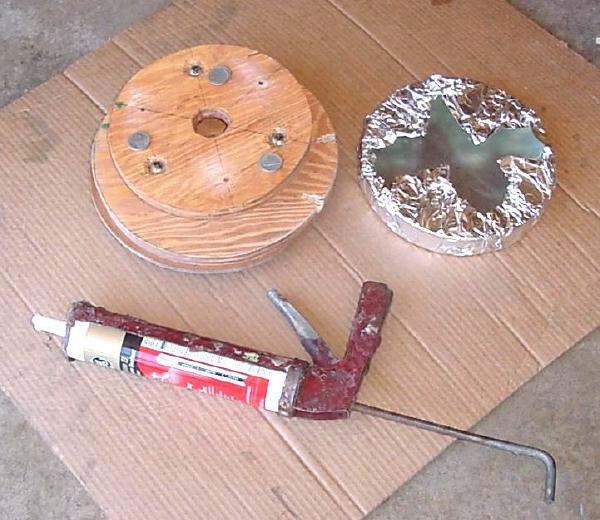
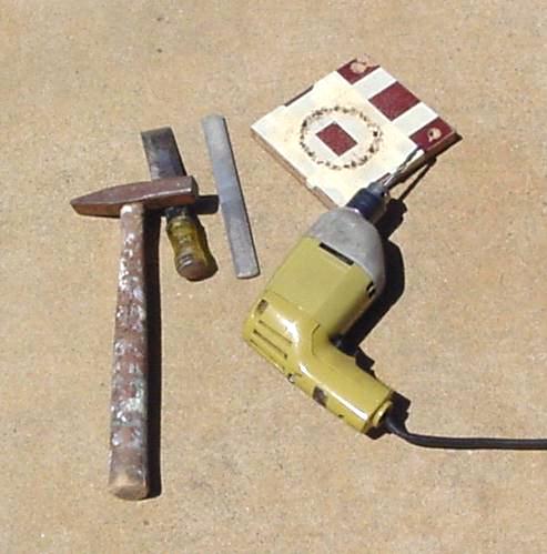
Here are the materials for attaching the tiles to the concrete tool. These one inch square tiles come in sheets pre spaced. The most expensive part of this buy is the tile nippers, $20 and the epoxy, $19. |
 |
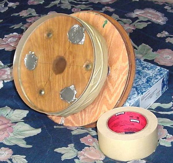
We smeared the mirror face with grease again and smoothed aluminum foil onto the grease. |
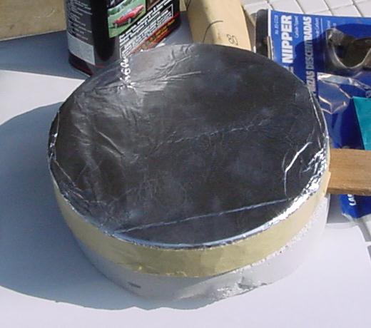 |
And taped the mirror sides and back with masking tape. |
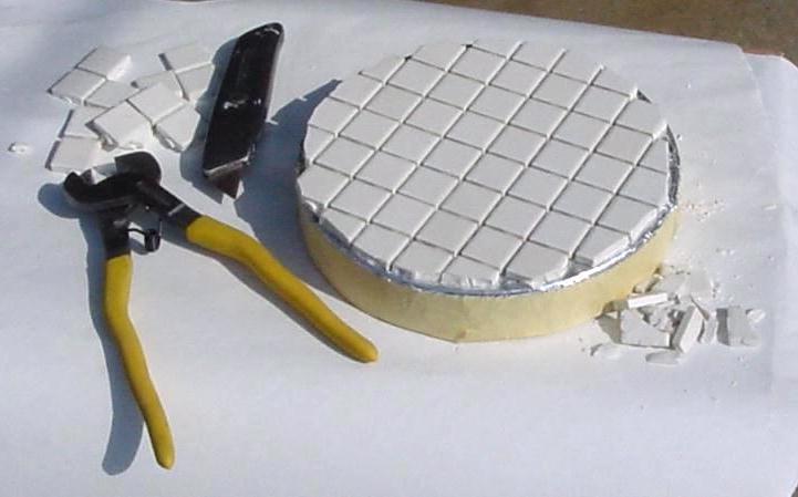 |
We cut the tile spacers to make an 8 inch circle then nip off the tile corners that overhang the mirror edge. The tile edge should be a bit smaller than the mirror. We did not cut any of the tile spacers within the 8 inch area for this mirror. Had we made a larger mirror with short radius of curvature the flat sheet of tile would not have lain against the curved mirror unless some of tile spacers in the center of the tile sheet were cut. |
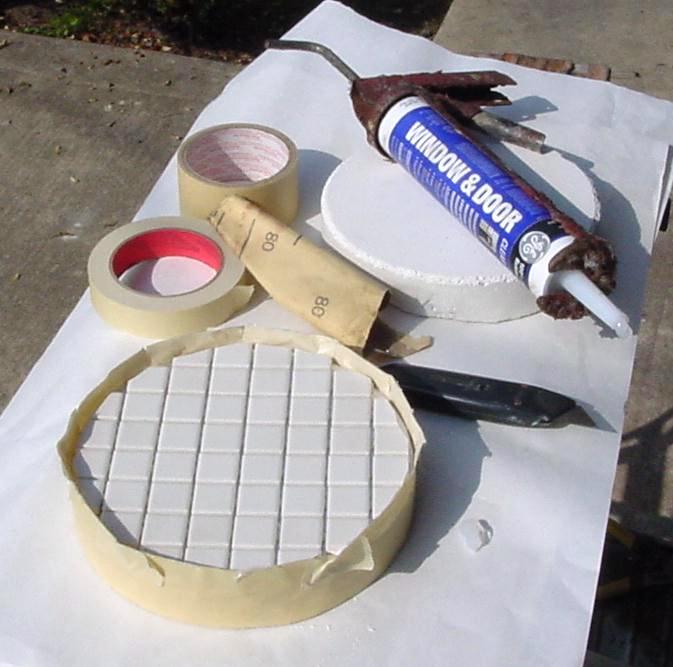 |
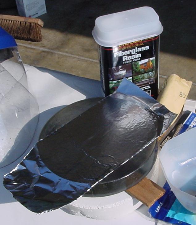
Here is the mirror with a mold rim formed of masking tape. The mold rim was too small for the concrete disk so we slit the edge and spread the rim and added masking tape band aids. Then to make the masking tape un sticky we squeezed a bit of silicone sealant on our finger and smeared it lightly around the inside of the mold rim. |
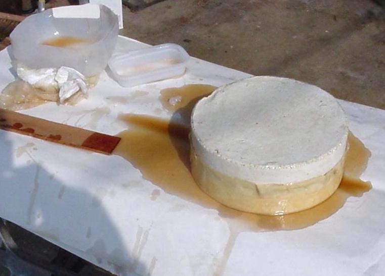 |
We smear the concrete disk with mixed epoxy and pour the
remaining epoxy into the mold then lower the concrete disk into the mold curved side down onto the tiles.
Careful it's slippery. Opps, we mixed a bit too much epoxy and it spills
over the masking tape rim. Working with epoxy is
not child's play. The acetone peroxide hardener will cause glaucoma and
permanent blindness if you get it in your eye. The resin should be
cooler than 60 degrees F before you mix in the hardener. The resin warms
as it hardens and can go into thermal runaway and burn up. By starting
cool the fuel supply will be reacted before thermal runaway. Although epoxy resin works well there are other methods for attaching the tiles. |
 |
No problem separating the mirror from the tool. We cut a sheet of 60 grit sand paper into six squares and after the epoxy has cured about half an hour we sand the edge of the tool to bevel the tiles. The yet soft epoxy is easy to sand. |
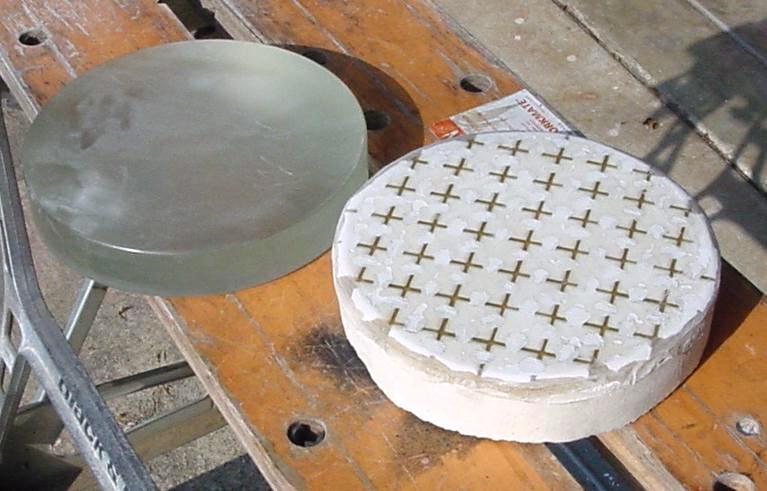 |
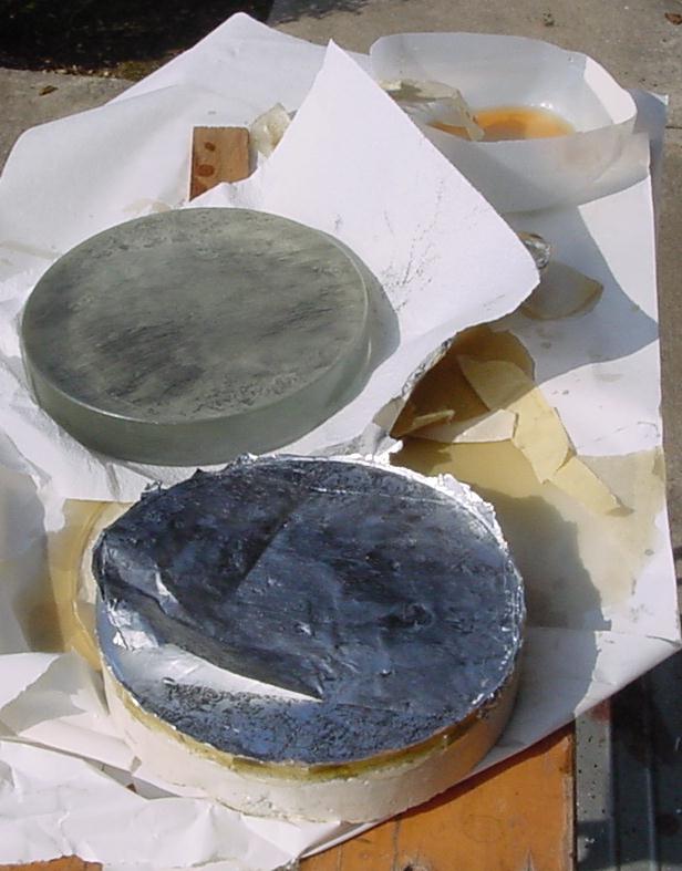
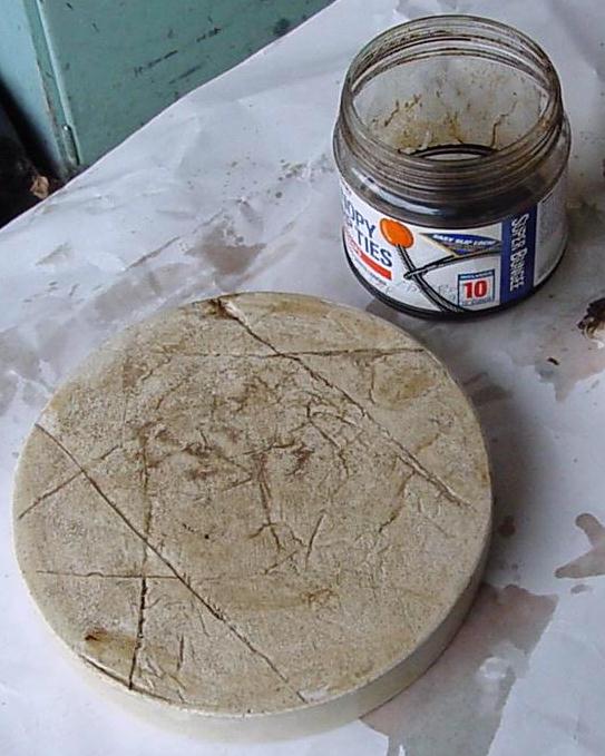
Here is the roughed out mirror and full size tool ready for use. We have preserved the original bevel of the Pyrex blank so there is little need to bevel more. If the mirror edge becomes sharp we can touch it up a bit. |
 |
For the first hour we are mostly removing tile spacer and epoxy with 100 grit. We are able to chip some of it away with a pocket knife after grinding a while. |
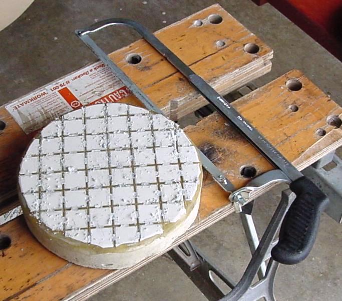 |
We remove a bit more epoxy from between the tiles with a hack saw. The channels don't need to be very deep. After another half hour with 100 grit the curve is beginning to shape up. |
 |
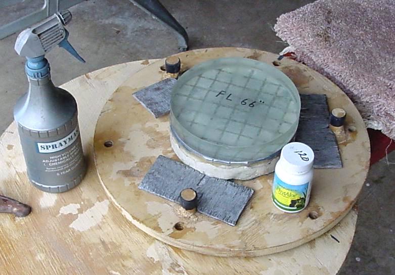
At the Chabot Telescope Makers Workshop they measure the
curve with a sphereometer and find the focal length to be about 66
inches, longer than I wanted. Here we find that the mirror depth at the
center, called the sagetta of the mirror, is about the thickness of a penny for
an 8 inch F 8 mirror. The sagetta of a quarter would be better for a general
purpose telescope. I used the 5 inch disk about a half hour longer across the mirror center using 100 grit to shorten the focal length a bit more. Then I worked with the mirror on top of the full size tool, working around the edge with 1/2 inch overhang for about 30 minutes to soften the shoulder and shape the tool edge. In this picture the mirror is shown as after fine grinding. |
 |
This picture was added later.
We found out later during polishing that the mirror edge had not been completely ground to the curve of the rest of the mirror. A friend told me that to find if the mirror is ready for 220 grit to mark the mirror with a pencil and grind a few short strokes with 600 grit. If the pencil or marker is not removed at the edge or the center ( or anywhere else ) don't go beyond 120 grit. A few minutes more grinding with 120 grit equals a hundred hours of polishing. If grinding mirror on top won't affect the edge then grind with the tool on top for a while and then finish with more mirror on top. The marker pen test can also be used for testing when the mirror is beyond 400 grit but it is necessary to use a red marker and not the black marker because the black marker contains solid particles. It is also helpful to apply the marker just before quitting for the night so the marker can dry completely. If the marker comes off evenly with the next finer grit it may be possible to shorten the time with that grit. |
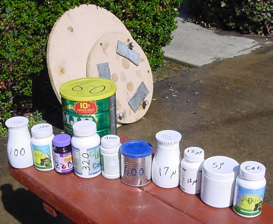 |
Here we see all the grits and the CeO used for making the
mirror. These came from the Telescope Makers Workshop. 120 grit, 45 minutes, slight "W" stroke. See Note! Touched up the bevel with 220 sand paper and a block. 220 grit, 1 hour 10 minutes. 320 grit, 1 hour. Inspected for sparkles caused by rough grinding pits. 400 grit, 50 minutes. Inspected again, compared edge to center. 30 minutes more with 400 grit. 600 grit, 1 hour. |
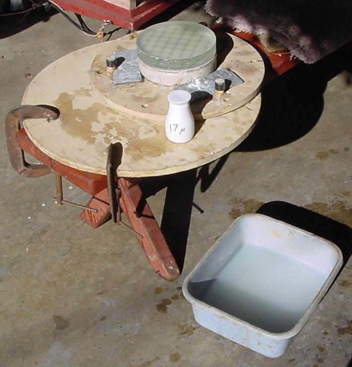 |
Starting with 400 grit we begin to notice that it takes
some time for the water to squeeze out from between the mirror and
tiles. Until the water squeezes out the mirror is floating on a film of
water. Be careful lowering the glass onto the tiles and go slow until
the grit spreads out. After adding more grit to grind up about three times rinse it all off in the pan of water and start fresh. The water in the pan should be warm. 17 u ( micron ) alumina grit, 1 hour. Work a bit slower and if friction begins to increase wash the mud off in the water. 12 u alumina, 45 minutes. 5 u alumina, 45 minutes, optional. Shortens polishing time. Go slow to keep from seizing. The lubricating water layer is now very thin. Often we have noticed that people have trouble getting the outside half inch of the mirror to polish. To avoid this problem you might want to work the mirror half an inch over the tool edge part of the time during fine grinding. |
Why does it take so much longer for some people to get to polishing than others?
Watching the people that grind for a long time you can see some of the reasons. Often they are grinding at a table and must twist their back while grinding. Going slow feels less stressful. Another reason- the more grit the faster, right? Wrong, the extra grit just gets in the way. If you can't hear the faint ring of the grinding while fine grinding the grit is probably lifting the mirror off of the tile tool or has become too finely pulverized to do anything. Keep your plastic rinse pan in easy reach. Use enough grit so that it can be all over the tool surface and go slow until the grit spreads out then go at it. It won't take long to grind the grit then add a bit more. When it gets a bit muddy rinse it all off in the pan. Rough grits will grind up more quickly than fine grits.
| Because of extra polishing needed to remove pits at the mirror edge I will fine grind longer next time. Shortening the focal length with the five inch tool after using the full size tile tool should have been followed with some grinding with the full sized tool on top to bring the new deeper radius to the mirror edge. | ||
| Grit | Grind time. | Would have ground. |
| 120 | 45 minutes | 90 minutes |
| 220 | 70 minutes | 75 minutes |
| 320 | 60 minutes | 75 minutes |
| 400 | 80 minutes | 75 minutes |
| 600 | 60 minutes | 60 minutes |
| 17 micron | 60 minutes | 60 minutes |
| 12 micron | 45 minutes | 60 minutes |
| 5 micron | 45 minutes | 45 minutes |
Mr. Dobson doesn't use so many different grades of grit and you can skip grades if you don't have them. I can't give an estimate of how overall grinding time will change in that case.
Experimenting with the fine ground mirror.
 |
|
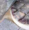
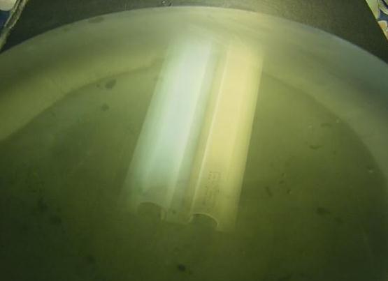
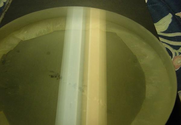
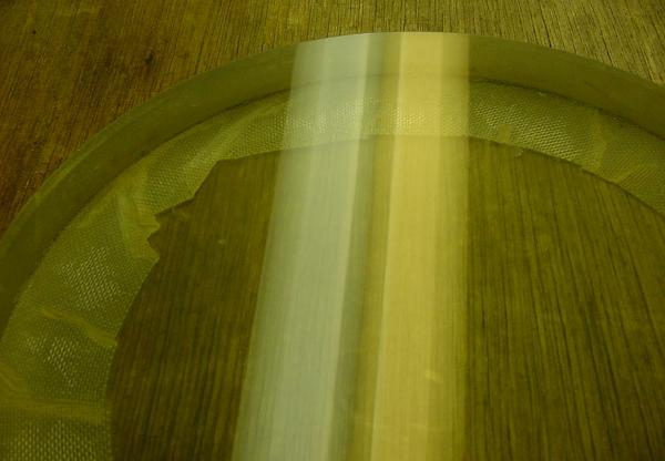
Although the mirror has not been polished there is a good reflection at a grazing angle. As the angle of reflection becomes steep, as the picture on the right, the reflected light is more amber. The short wave length blue light is scattered by the yet too rough surface. X-ray telescopes often use grazing angle mirrors to reduce the x-ray absorption and scattering. |
'Polishing Out' an Eight Inch Pyrex Mirror Blank
and Building the Telescope
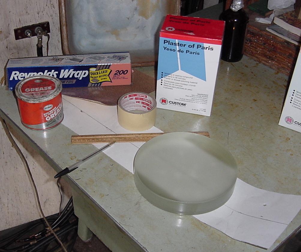 |
Almost everyone pours the pitch lap on the old grinding tool but just to be different we decided to pour a plaster of Paris disk on which to make our pitch lap. Here are collected the materials. In order to get the disk to be of equal thickness at all edges we were careful to cut our poster board mold strip to be even and the proper height. |
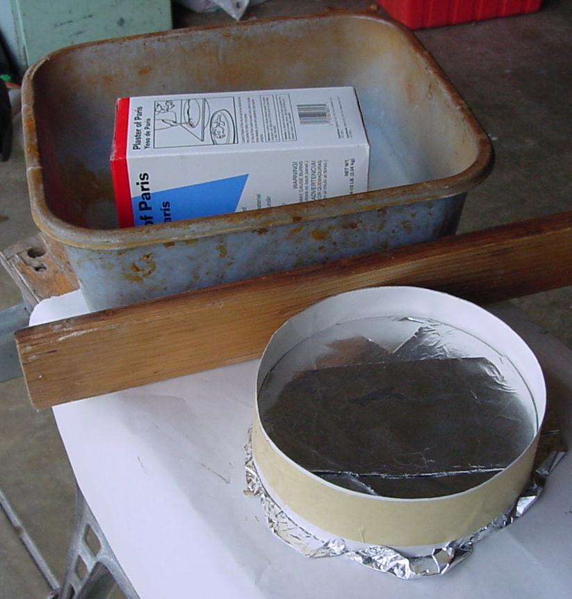 |
We greased the mirror and laid aluminum foil strips across it to make sure the plaster of Paris would not stick. Then taped the poster board tight around the mirror. |
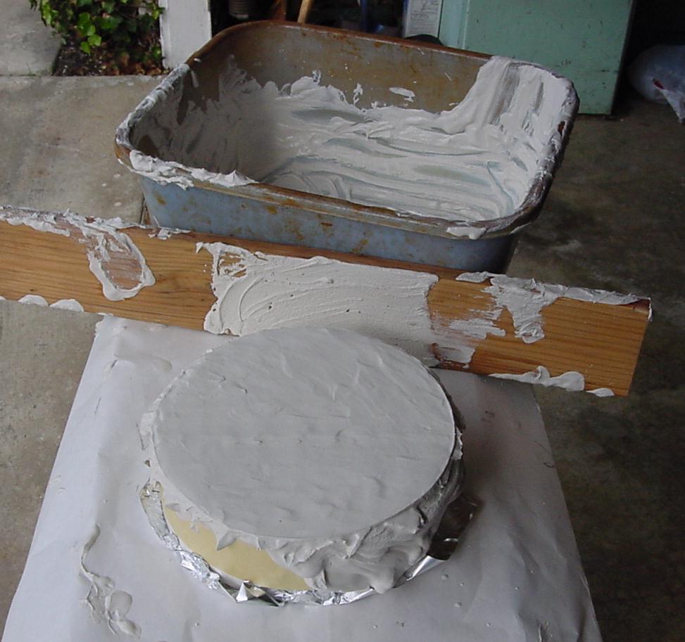 |
We mixed the plaster of Paris with our hands and filled the mold. The stick does not work so well for smoothing the plaster so we washed our hands and smoothed the plaster with our wet hands. Working time about 10 minutes. After cleanup we waited about 40 minutes to separate the mold. We lifted the plaster carefully but the mirror stuck then separated all at once falling about an inch to the wood table. After trimming the flash with a pocket knife we cut a sheet of 80 sand paper into six squares and beveled the edges slightly and leveled the bumps. Rubbing and peeling we removed the wet poster board and foil. Careful when cleaning the mirror with paint thinner. Its very slippery. After leaving the disk in the damp for a day we brought it in the house to dry for a few days. |
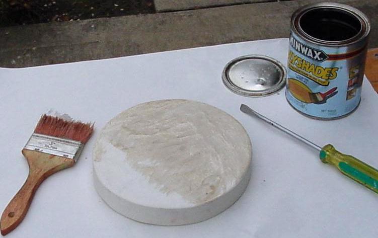 |
The disk is quite dry and we paint it with Minwax polyurethane. Leave the curved face un painted. |
 |
The next day we smear the curved side with pitch dissolved in a bit of paint thinner. |
 |
Some weeks later I take the mirror to the San Jose Astronomical Association to pour the pitch lap. By now you know I'm not a telescope in a day person. |
 |
At home again we texture the pitch lap with a plastic
screen.
After doing a light press we polish for 15 minutes. Polish fast enough and with enough pressure that after 3 or 4 minutes of polishing the pitch will warm and begin to grab. Then we rest out hands for a minute or two. |
 |
After only 15 minutes polishing the mirror center shows some polish. The mirror edge looks totally unpolished but we are able to get a bit of reflection even at the edge. |
 |
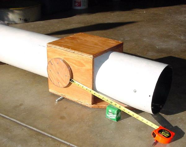
This is the cue to measure the radius of curvature or focal length so we know how long a cardboard tube to buy and how big the diagonal will need to be. For an 8 inch scope we will use a 10 inch diameter tube. The radius of the tube is 5 inches. We already know the type of focuser we are to use. With that focuser the primary image needs to be 2 1/4 inches outside the tube. Measuring we find the Radius of Curvature of our mirror is about 125 inches. The F# is 125 divided by 2 then divided by the mirror diameter, 8 inches. Or about F7.8. To find the diagonal size divide ( 5 + 2 1/4 ) by F7.8. Equals .93 inch. Not every star is exactly in the center of the field so add .5 inch so stars near the edge of the field won't be dim. Equals 1.43 inch. The catalogue lists a diagonal of 1.5 inches so that will be just big enough. You should also order the 100 line per inch, 1 x 1 inch Ronchi grating at this time. |
 |
In years past I would probably have just kept polishing
with the mirror on top for a long time. I know now that very little
glass is removed at the mirror edge with the mirror on top so I polish
for 15 minutes with the mirror on the bottom. Be sure to rinse off the
pitch lap in the plastic pan before putting it on top of the mirror.
Then since I have the lazy Susan and the weegee lap I polish just inside the edge with the weegee lap for 15 minutes. I have no idea what this is doing to the mirror figure but since there is no area of the mirror that is completely polished the figure is not important. |
 |
Now there is a definite polish everywhere on the mirror except at the very edge. It is presumed that the edge is high since the weegee lap was not polished over the edge. To quote a past mirror maker, "There is nothing so temporary as a turned up edge". |
 |
If you are following chronologically at this point we
began building the scope. We got as far
as cutting the altitude bearing circles before returning to polish.
Second polishing session:
Third session:
The polishing results are as at left. The mirror appears to be almost 'polished out' except at the very edge beyond where we polished with the weegee lap. |
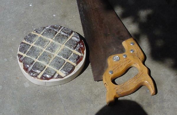 |
Since we did a light press before each session the
grooves have begun to close so we use the saw to deepen them. The
Wellmann-Bell pitch seems to chip less than the black pitch or maybe the
temperature is warmer.
Be sure the pitch lap is warm and the saw is cleaned before trimming. |
 |
Forth session:
Weegee polishing over the edge of the mirror, 15 minutes Mirror on top, 30 minutes The mirror now looks polished out. Since we presume to have no test equipment we will need to finish the telescope before figuring the mirror. If you add up the time for 'polish out' above you get three hours. The time it actually took is about six hours because of equipment setup, mirror pressing before polishing and resting while the pitch cooled from heavy fast polishing. |
|
Building the Telescope |
|
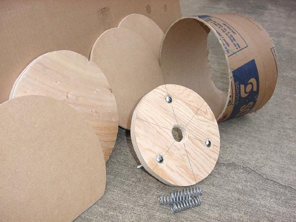 |
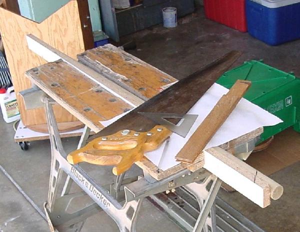
The tube we bought was a bit long and had a bum end so we wrapped a paper around the tube to make a mark and sawed the bum end off with a hand saw. Here are the parts for the partially built mirror cell. The hole in the mirror backing plate is to improve air circulation. The two extra pressed board disks are for a telescope cover for the top of the telescope. |
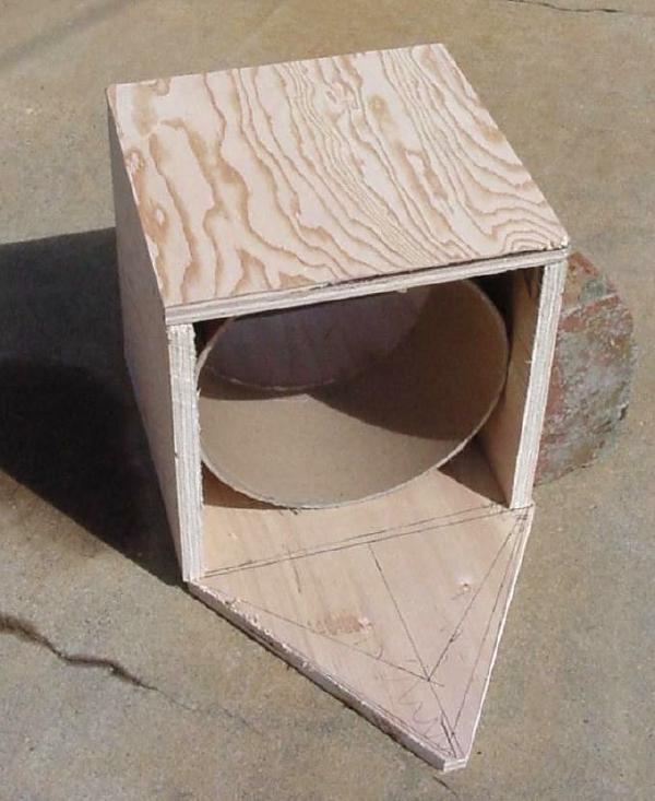 |
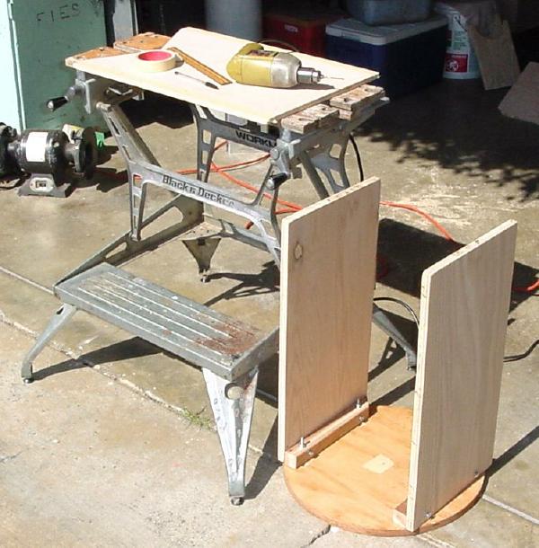
Here are the parts for the tube box. Since the size of the telescope base depends on the size of the tube box we want to make sure the tube box is the right size. The tube box needs to be big enough that the tube can be slipped in after the box has been glued. Next we pilot drill and counter sink for five #6 x 1 5/8 inch deck screws at each edge. Next the tube box parts are sanded and sealed with polyurethane stain. After the stain has dried we glue and screw the tube box together. |
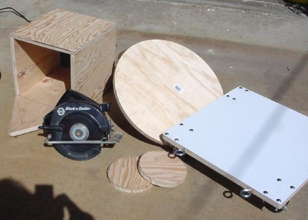 |
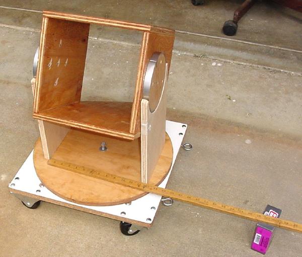
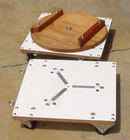
Here is our ground board cut from coated particle board
with the wheels installed. Two wheels run straight, the other two castor.
The 18 inch circle was bought precut from OSH. Not knowing the diameter of the
altitude bearings we referred to the Side
Walk Astronomers website and then cut and sanded the altitude
bearing circles to be about 6 1/4 inch diameter.
Power tool safety is beyond the scope of this program. Keep in mind the cost of one trip to the emergency room would buy a better telescope than we could possibly build. Now we go back to mirror polishing while the glue and stain dries. |
 |
We went beyond the normal Dobsonian design and
installed a band around the tube bottom as a reinforcement for the
mirror cell mounting screws. The band is held by two #6 screws with nylon
friction nuts and with silicone sealant. The nuts serve to index the mirror cell.
Put a bit of masking tape on the mirror cell back plate and press it in
against the bando nuts. From the indentation in the tape you can
tell where the notch for the bando nuts will need to be. Then drill a
few small holes to make cutting the notches easier. The mirror cell mounting screws are #10 x 1 1/2 inch Phillips pan head sheet metal screws. After the sealant cured we pre drilled three undersize holes through the bando into the mirror cell back plate then re-drilled the bando with a clearance drill. |
 |
After sanding we had the sheet metal shop cut
and roll a stainless band to go
around the altitude bearing disks. Cut sheet metal edges tend to be very sharp so dull the edge with sand paper. Here we are gluing the band to the disk with sealant. |
 |
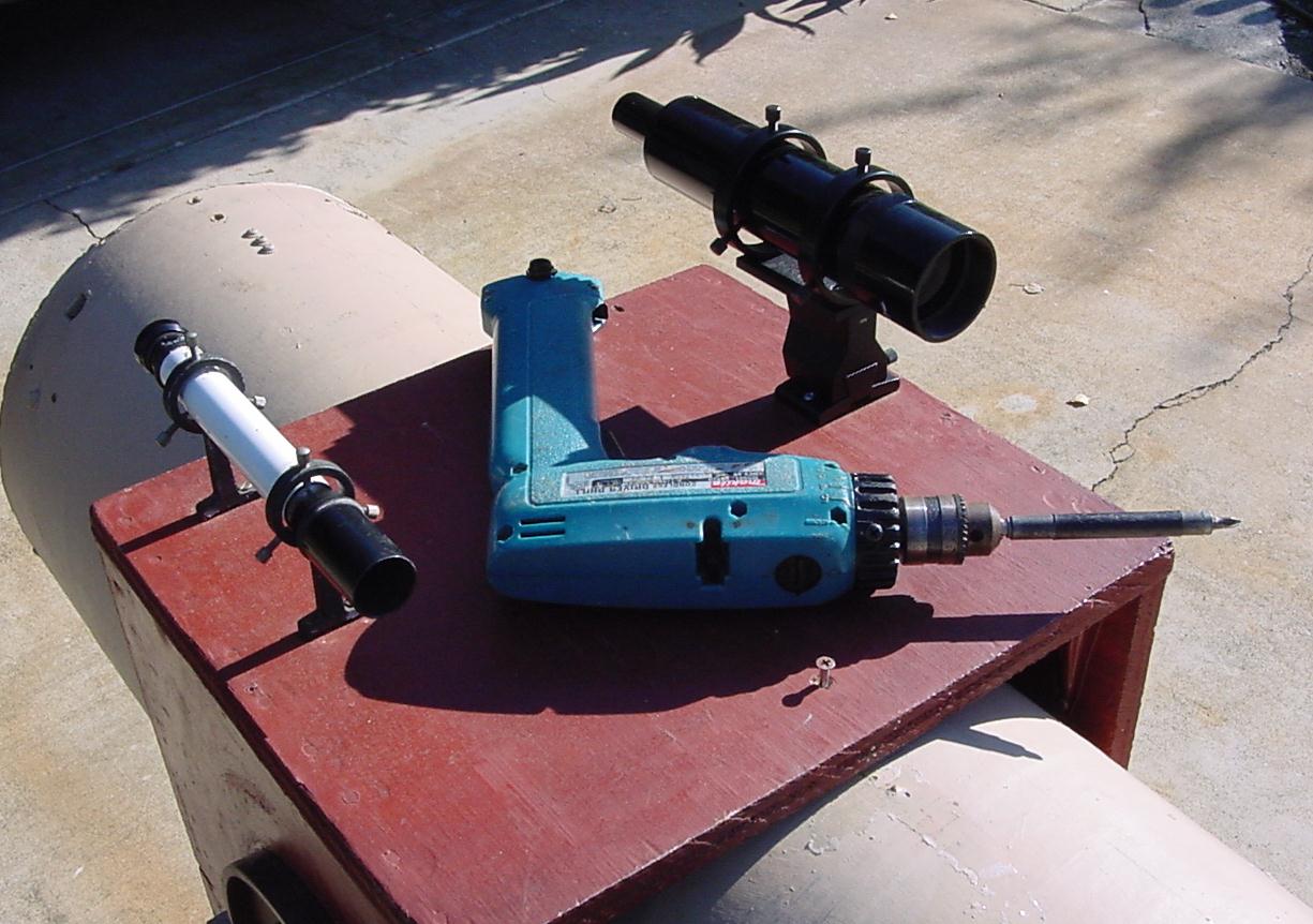
We draw a center line parallel to the telescope tube on the side of the tube box. We measure back along the center line the radius of the altitude bearing ( 3+ inch ) + 1/2 inch from the star-ward edge of the tube box and drill an undersize hole. Then we drill an undersize hole in the center of the bearing disk and insert a screw so that the tip of the screw sticks out 1/8 inch. Insert the screw tip in the hole in the tube box and tighten the screw. Before installing the other four screws make sure the altitude bearing slot will not try to ride over the Teflon cradleboard bearings when the scope is tipped up and down. Note that if you plan to use a heavy finder scope you may want to offset the centerline on the tube box 1/16 inch to maintain balance when the tube is tipped up. If the centerline is high the tube box is low with the tube tipped down. |
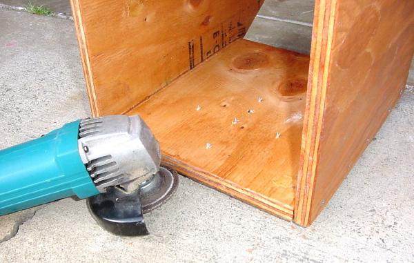 |
The screws were a bit long so we grind off the sharp tips. The sparks from the grinder are hot enough to melt pits in your glasses so use eye protection. |
 |
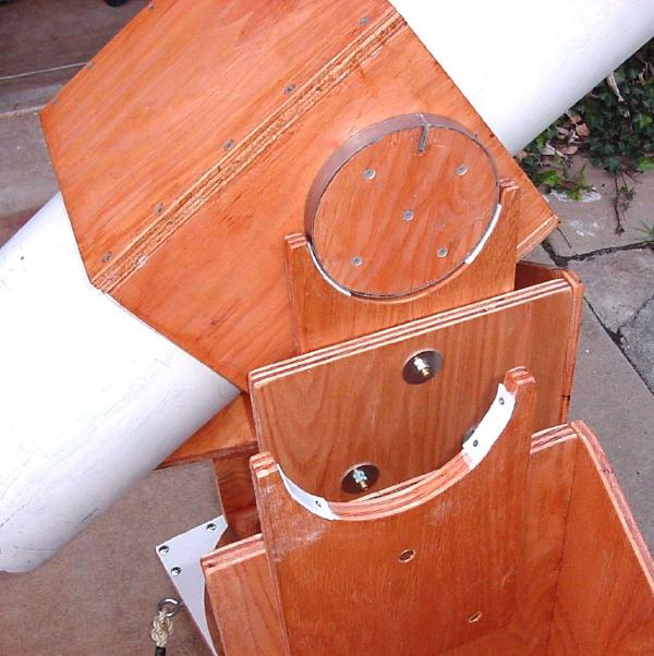
Here we have cut the cradle boards. While we were at the sheet metal shop we had them cut a 16 inch diameter galvanized sheet with a 3/8 inch hole in the center. A true Dobsonian would have used an old phonograph record or antique hard drive disk. It appears the 18 inch diameter rotating base will ride over the inner wheel mounting bolts so we remove the inner bolts and sink them a bit. As it turned out sinking the bolts was unnecessary. |
 |
We worry that somehow the cradle boards will end up too close together or too far apart. Here we shim the cradle boards with washers to test the clearance. |
 |
Now we have the measurement that will allow us to complete the base structure. Keep in mind that plywood that looks to be 3/4 inch thick may actually be 23/32 thick. |
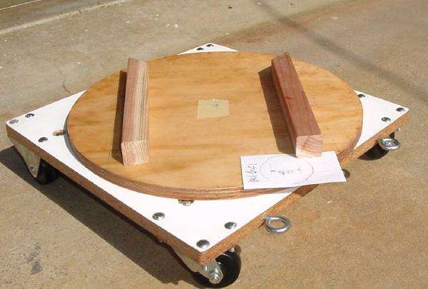 |
We find the rotating base center and make a center line for the structure. Then carefully lay out the location of the structure sides either side of center and the position fore or aft. The fore and aft position is adjusted to center the structure on the 18 inch plywood disk. |
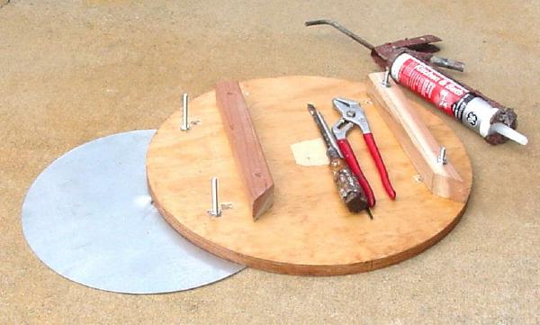 |
Since the heads of the flat head screws will be inaccessible under the sheet metal disk we decide to bolt and glue them in permanently. Now we will notch the plywood disk and the redwood 1 1/2 x 1 1/2 for the retainer nuts. Seems awkward but this will allow the redwood to be removed later for adjustment or painting. |
 |
We are actually building one 8 inch scope ( F7.8 ) and completing a second 8 inch scope ( F 6.5 ) built by someone else. Here we measure to try to get an idea of the height of the bottom of the cradle above the rotating base. The final decision is to use the full two feet height of the 2 foot by 4 foot quarter sheet of plywood for the structure sides. Later after the telescope is complete we will cut down the height of the two foot sides after measuring the completed telescope. |
 |
After assembling the structure sides we cut the structure web to fit using 1/2 inch plywood. |
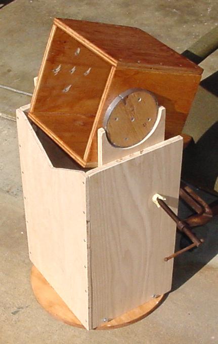 |
Locating the cradle boards is a bit tricky so we 'C' clamp the cradle board temporarily to have a look. The first thing to determine is the distance of the cradle board from the web. See picture below left. If this distance is too small the scope will not tip all the way up to the zenith. We draw a vertical line on the inside of the structure side the proper distance from the web for the purpose of locating the cradle board. Next we slide the cradle board up along our line until the lower star-ward corner of the tube box will clear the web. See picture left. |
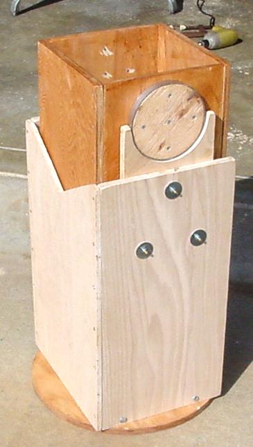 |
If the height of the cradle boards is not the same the tube box will bind. By using three flat head 1/4 inch screws with fender washers for each cradle board we can make small adjustments by filing the holes in the structure sides. Later we will put brass cap nuts on these screws. |
 |
We glued the sheet metal disk to the plywood disk with silicon sealant with a 3/8 lag bolt through the hole to keep them aligned while the sealant cured. Silicone sealant takes a long time to cure when used in this fashion so make lines of sealant with air space between. A standard Dobsonian design would have three Teflon pads tacked to the ground board with finishing nails. The distance of the pads from the center lag bolt determines the azimuth friction. Too little friction and the azimuth will never stop changing. |
 |
We screw down three aluminum strips radiating from the
center axis. Then screw down strips of Teflon to bridge across the
strips in three places. We used over sized washers on the flat head wood
screws. The axis bolt is tightened snug on its washer then loosened 1/4 turn so the rotating base can rotate without binding. |
 |
There was a bit of problem with the cradle board Teflon. The stainless altitude bearing would bind on the screws that retain the Teflon. We glued in tin can under the Teflon center but that was still not enough. Finally we removed the pads and filed the cradle board at the Teflon retainer screw holes. That fixed the problem. Newer designs often use a 'V' shaped cradle to avoid this problem. |
| Since we now have all the parts to complete the Club's 8 inch F 6.5 scope that had been partly built by someone else we decide to complete the Club's telescope first. The Club's scope. | |
 |
Now back to the 8 inch F 7.8 scope we are
building from scratch.
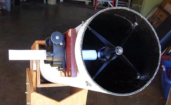
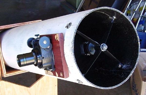
Here we cut the 1 1/8 inch dowel at a 45 degree angle for the spider. |
 |
Select three good shingles then shift them so the thin ends are equal thinness and cut slightly concave with scissors. Gluing the shingles into the dowel with silicone seal. Adjust it flat on a table then let it sit overnight to cure. |
 |
After trimming the spider legs for the tub we find we are about 1/16 inch undersize. We add to the ends with 3 x 5 card dipped into glue and water and folded over the edge. The next day its still a tad small so I run a thin bead of sealant on the end and pinch it off with my fingers. Now it sits in the tube wherever it is placed. After the black primer paint has dried I glue the diagonal I bought. The spider needs to be firmly attached to something to make gluing the diagonal possible. |
 |
To position the diagonal properly you must check the positioning from three directions. After the sealant has cured we huff it off and wrap it in lens paper for use later. |
 |
Today we prepare the mirror and cell for mirror testing in the telescope. I mount the mirror as described in simplcl.htm except that I wrapped the mirror back with aluminum foil first. At the end of the week I removed the mirror from the foil and striped the extra foil away from the silicone pads. |
 |
I tape the edge with 2 inch masking tape and it is ready for testing as soon as the focuser and tube are finished. |
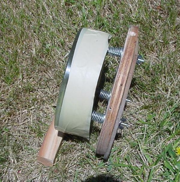 |
Next step is to cut the tube to the proper
length. Here we adjust the mirror cell's springs to the
middle of their compression range with the wing nuts before installing
the cell in the tube. We will need to
know the distance from the center of the diagonal to the star-ward edge
of the spider. If the tube is cut too short there will be no support for
the spider legs. Measuring the spider we find that it is less than 3
inches and we want the tube to extend at least 6 inches above the eyepiece
tube. So the spider is not a factor.
The next question is about how far is it from the mirror face to the eyepiece hole. We need the distance from the diagonal center to the eyepiece focal plane for this and we don't yet have the focuser to measure. So we will say the focal plane will be 2 inches outside the tube. The tube radius is 5 inches plus the 2 inches minus the mirror focal length which is about 62 inches = 55 inches for the eyepiece hole. So add the six inches from the hole to the top of the tube and we get 61 inches. So the distance from the mirror face to the top of the tube is roughly the mirror focal length. Most Sidewalk Astronomer telescopes are used in lighted areas so we can use a bit extra tube length. |
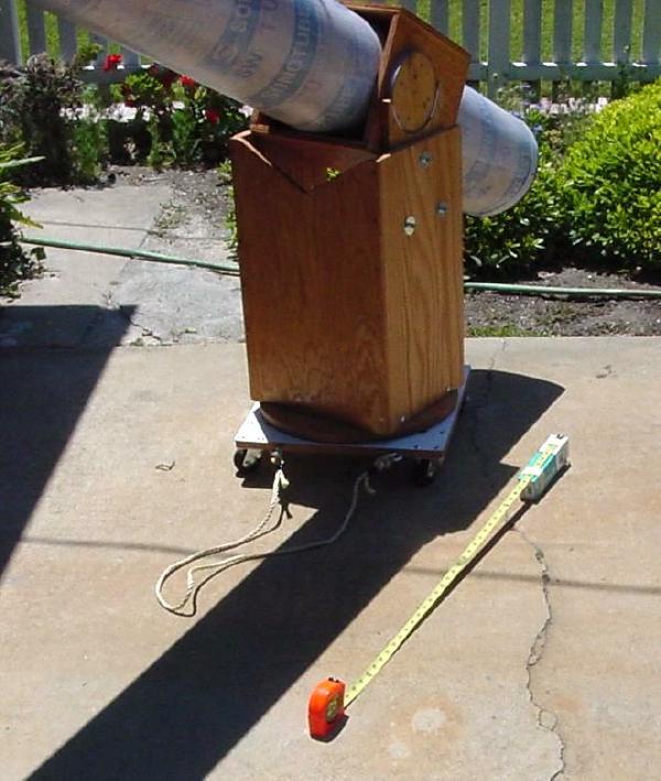 |
We tape an old box for vacuum grease to the end of the tape measure. Then lower the tape down the tube until the tape touches the uncoated mirror. The distance from the face of the mirror to the top of the un-cut tube happens to be 85 inches. |
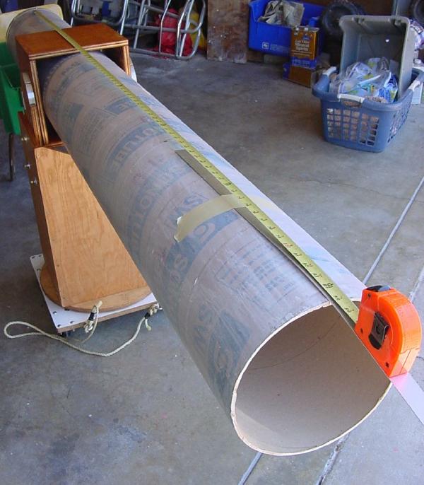 |
Now we tape the measuring tape to the outside of the tube with the 85 inch mark at the top of the un-cut tube. At 62 inches on the outside of the tube we make a mark. |
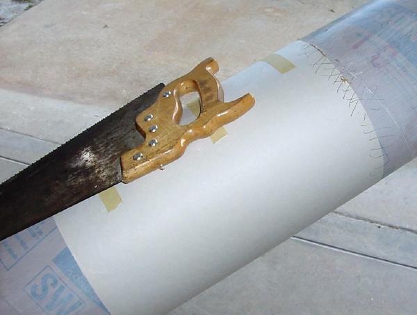 |
To get an even cut line we wrap a piece of paper around the tube. |
| Completing our
F 7.8 home built telescope. |
Since this web page is getting a bit long,
we will start a new page: 8_inch-b.htm On the page 8_inch B we will do the following jobs: |
Completing the partly built 8 inch F 6.5 telescope.
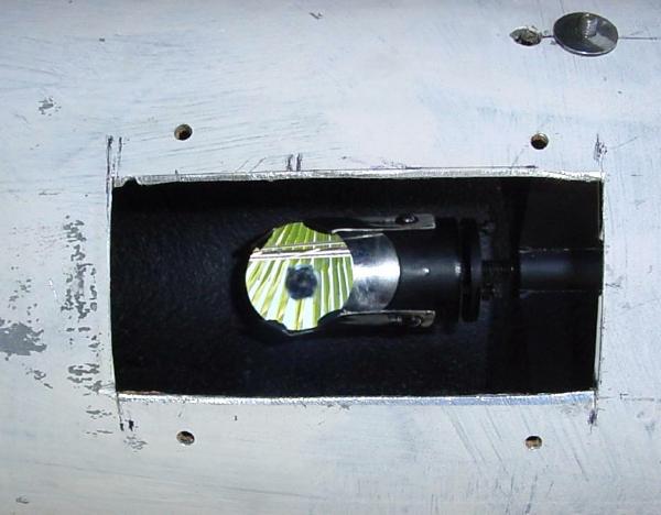 |
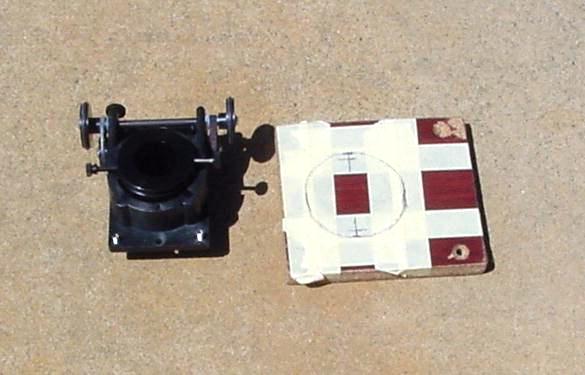
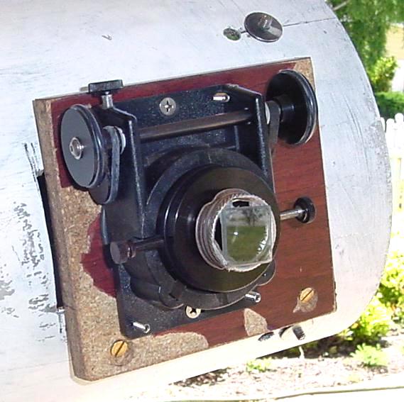
The original telescope had a focuser more suited to a long refracting telescope. The focuser held the eyepiece so far out from the tube that the diagonal was almost too small. We bought an AstroSystems Phase 4 Focuser to replace the original. Luckily the original tube was long enough to move the mirror back about 3 inches and the spider up about 3/4 inch. Rather than trying to patch the original eyepiece hole we cut out a rectangle from the tube and made a piece of pressed board to mount the new focuser. |
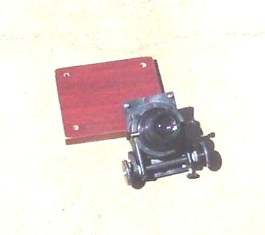 |
Here is the new focuser and the mounting board. |
 |
Adjust the mirror cell adjustment bolts to the middle of their range of adjustment by observing the compression of the mirror cell springs. After holding the new focuser to the tube and making some careful measurements to determine how far up the telescope tube to cut the hole we traced around the new focuser onto masking tape. |
 |
Then drilled many holes just inside the line. Then drilled again at an angle. Finally after a bit of chiseling the center could be knocked out. The fine work was then completed with the rasp and the two mounting holes drilled. Then I dipped the board into thinned polyurethane to seal and harden it. |
 |
Rough collimation with a rolled up piece of printer paper. Since we had an Orion laser collimator we finished with that. |
 |
The focus was fine on objects a few hundred feet away but just came into focus at the limit of inward travel when focusing on distant objects. Luckily we found the mirror cell springs were compressed and loosened the tailgate adjustment wing nuts a bit. |
 |
Here we use the Ronchi grating to test the mirror that came with the scope. We tested on a power pole insulator but were unable to get a picture of that due to the low contrast and the difficulty of seeing the Ronchi lines in the camera's LCD display. |
 |
So we used the laser and the mirror in the tree at night to obtain these pictures. Even at night there are plenty of heat waves. I decided that the scope had a good mirror, at least as good as the test I was using. The artificial star in this test is about 250 feet away from the scope. |
|
We were able to cut 5 1/2 inches from the bottom of the structure sides and web and still have about 1 1/2 inch to spare in case of future tube rebalancing due to the addition of a Telrad or camera. Cut off too much and you will be raising the cradle boards later. |
Telescope Upgrade
|
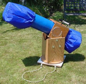 We have
completed the upgrade of one of those old scopes you have seen in the
CSM Planetarium.
We have
completed the upgrade of one of those old scopes you have seen in the
CSM Planetarium.