alt_51.htm
This file explains the diffraction pattern seen at the telescope eyepiece at night when the air is very still and stable. The file also has more information about testing with an eyepiece. Note, it is not necessary to understand diffraction theory to build a good telescope.
Table of Contents
The Diffraction Pattern
The Daytime Terrestrial Telescope
The Light Bucket
The Space Telescope
Encircled Energy
The Point Spread Function
The Modulation Transfer Function
Good Seeing
More About Testing At The Eyepiece
Misalignment
Tube Currents
Spider Diffraction
Pinched Optics
Spherical Aberration
Turned Down Edge
Zonal Aberrations
Rough Surface
The Diffraction Pattern
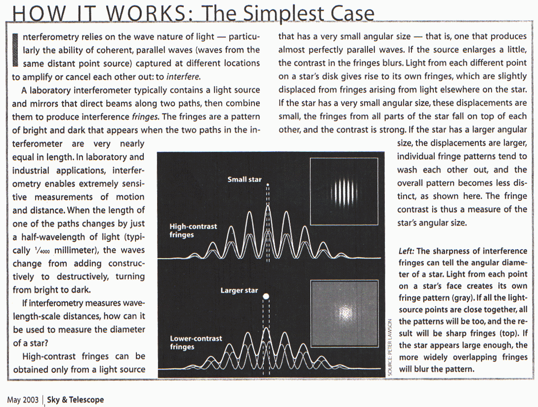
The diffraction pattern of a perfect telescope in space will be a central bright dot surrounded by concentric bright rings. The rings decrease in brightness the farther they are from the central disk. An expert double star observer can tell that there are two stars instead of one even when the second star is inside the first diffraction ring of the first star. Looking at a single star, moving the eyepiece inside or outside of focus causes more diffraction ring to appear and the central Ary disk to go alternately bright and dark as the energy is spread into an ever larger circle. The telescope maker knows the appearance of the diffraction disk an equal distance inside of focus or outside of focus should be the same. A telescope that is optimized for double star observing loses little by having the center of the primary mirror shadowed. Shadowing the center of the mirror makes higher spatial frequencies more dominant resulting in a tinier central Ary disk. Shadowing the center of the mirror also causes a larger portion of the energy to be in the diffraction rings.
On the other hand any planetary image is no more than the mosaic of overlapping diffraction patterns formed on the retina of the observer's eye, each pattern corresponding to a separate point of light on the planet. Therefore anything which will increase the sharpness of an individual diffraction pattern should also increase the sharpness of planetary detail. Ref(1) In planetary observing light that is in the diffraction pattern outside of the central Ary disk has the effect of reducing contrast. Many of the surface features on the planets and moons have very little brightness and color differences from adjacent areas and this means that any loss in contrast will make them imperceptible. Thus a planetary scope benefits greatly by keeping the light in the central Ary disk and not in the rings even if this causes the central Ary disk to be slightly larger. It is possible to change the reflectivity of the primary to increase the ratio of the energy in the central Ary disk compared to the energy in the diffraction rings. This concept known as apodization was popular at one time but the advantages for planetary observing seem to be elusive. Apodization is worth mentioning since the concept may prove to be more useful with radio telescopes.
Before radio telescopes and before the Space Telescope the red giant star Betelgeuse in the winter constellation of Orion was the only star that had been resolved in a telescope and then only as a spatial frequency and not as an image. Using the equivalent of a giant telescope on Mount Wilson in 1920 A. Michelson covered the entire surface of the 100 inch Hooker Telescope except for two small holes. They observed that the spatial frequency in the imaged diffraction pattern increase as the holes were moved farther apart. At some distance as the holes were moved apart the spatial frequency could no longer be observed because of the delay of the light wave from one limb of Betelgeuse behind the light wave coming from the other limb. Testing the apparatus on more distant stars showed that the observed effect was not produced in the telescope setup.
The Daytime Terrestrial Telescope
This telescope, a 3 inch refractor with a beautiful machined brass tube stands before a picture window on Telegraph Hill overlooking the San Francisco Bay. With its 80 power you can tell the class of a sailboat way over near Angel Island. For its intended purpose this telescope works well. In the daytime with the cool ocean breeze mixing with the warm air rising from the roof tops 80 power is all the magnification one can use unless the image is to become a complete blur. Light is no problem with patches of sunlight beaming down between wisps of advection fog. As an astronomical telescope this scope won't perform near as well as an amateur made 10 inch scope with a cardboard tube. Take this daytime telescope to a good dark location with still air and look at M13 Globular Cluster in Hercules and its disadvantage will become apparent. The diffraction pattern for each star in the cluster will overlap the diffraction pattern of other stars and increasing the magnification won't help. Increasing the magnification only makes the fuzzy globular bigger and dimmer and it was quite dim using only 80 power. After a while the shinny brass tube gets cold like the windshield on your car and if there is moisture in the air dew drops drip from the scope. Every object is radiating infra red energy. The infra red energy from the dark sky is like the infra red energy from something very cold. A black telescope will absorb infra red energy as does a black car in the daytime. The shinny brass tube reflects the infra red energy away and the tube cools until the convection of air around the tube keeps it from cooling further. The brass is a good conductor of heat and the inside of the top of the tube is colder than the inside of the bottom of the tube. The cool air at the top of the tube is heavy and continually sinks to the bottom causing more trouble by slowing the light waves unevenly.
The Light Bucket
The light bucket so named because the tube is proportioned more like a bucket than like the telescopes seen in the comic strips. A 10 inch F4 that is easy to transport. Looking at the Pleiades, which looks like the Little Dipper, but isn't, most of the stars fit into the eyepiece field at the same time. The stars are brighter than the sparkles of diamonds against the blackness of the sky. This is a special purpose scope and has some disadvantages. The diameter of the light beam coming from the eyepiece is likely to be larger than the pupil of your eye causing loss of light. If there are any errors in your eyepiece lens or in the lens of your eye this scope will make them more apparent. The curve of the mirror is very different from a sphere making correcting the primary difficult for the telescope maker. The sensitivity of the knife edge test increases with focal length so the short focal length is not helpful when correcting the primary. Stars near the edge of the eyepiece field of inexpensive eyepieces will have coma and astigmatism. Large observatory telescopes tend to be of short focus due to their large size and because they are able to use expensive correcting lenses and detectors other than the astronomers eyes.
Placing a telescope above the atmosphere removes all those problems with atmospheric turbulence and seeing. Errors in the surface of the glass and in the guidance system that would have been lost in the earth's atmosphere are now easily measurable. Those of us that like to continually make little adjustments and additions to our telescopes find it hard to imagine getting everything just right years before ever looking through the telescope. Not only is the design frozen before any astronomical work has been done but then the telescope is shaken by the solid rocket boosters during launch. Anything that will need fine adjustment after launch must have been anticipated years in advance. We will not try to review space technology here but we will review some of the concepts used in the original design of the primary and secondary mirrors for the Space Telescope. The discussion below presumes that we will try to get most of the diffraction pattern of a single star onto one CCD pixel. I have been advised that if the CCD pixels are arranged in triangles most of the diffraction pattern should cover three pixels. The pixels on most CCD chips are in squares which requires that the diffraction pattern fall on four pixels.
Encircled Energy
If one is to calculate the amount of a stars energy that can be placed onto a single pixel and how much is spread into adjacent pixels it is useful to know the amount of energy encircled within a particular radius from the center of the diffraction pattern at the focal plane.
The Point Spread Function
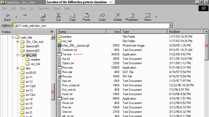
If you view the diffraction pattern simulator in the tele program you will realize that the diffraction pattern is different when different arrangements of primary and secondary mirror are used. Light that started from a white dwarf star 100 light years away would form a sub microscopic image in a 'perfect' telescope. In practice the image will be a diffraction pattern rather than an image of the distant star. If we say, for simplicity, that one unit of energy is supplied to our focal plane image by a particular primary mirror then that one unit could be in a submicroscopic point or spread over the focal plane in some way as in the diffraction pattern.
The Modulation Transfer Function
Presume we have a basic design for our space telescope and we would now like to know the expected performance of the telescope on an 'extended object'. We might want to know the detail that will be visible on Jupiter. Jupiter will definitely appear as an image on the focal plane and not as a diffraction pattern. Looking at a detailed photograph of Jupiter we see that there is fine detail and broad features such as the dark bands. So the type of plot we want is something that will tell us how the performance gets worst as the detail becomes smaller. To do this we will calculate the performance for one 'spatial frequency' at a time and plot the results on a graph. Fine detail is said to have a high spatial frequency. If one is to calculate the performance of the telescope to an object dominated by a particular spatial frequency one must first have calculated or otherwise obtained the point spread function for a star. If one wanted to test the performance of the telescope to an angle equal to the distance from the end of one dark band on Jupiter to the end of the next dark band for instance one would do a modulation transfer calculation for the spatial frequency corresponding to that angle. The result of the modulation transfer function for one frequency is found by multiplying the amplitude of the diffraction pattern by the height of the a sine wave at a particular point on the sine wave. The diffraction pattern is then multiplied by the next point along the sine wave. After this has been done for all the points along the sine wave the overlapping diffraction pattern are added together resulting in a new sign wave of lesser amplitude. As an example lets do a bit of the calculation for the bright area half way between the bands on Jupiter starting at 89 degrees along the spatial frequency sine wave. We will use a simplified diffraction pattern. Four tenths of the energy will be in the central Ary point. Two tenths two degrees ahead and two degrees behind the central Ary point and one tenth four degrees ahead and behind the central Ary point. The sum of the energy in the diffraction disk equals .1 + .2 + .4 + .2 + .1 = one. The sin of 89 degrees = .999 so we will add .1 times .999 = .0999 to the computer memory location for 85 degrees. Then .2 times .999 = .1899 to the memory location for 87 degrees, then .4 times .999 = .399 to the memory location for 89 degrees and so on. After this we move to 90 degrees and the sin = 1. We add .1 times 1 to the computer memory location for 86 degrees, .2 add to 88, .4 to 90 and so on. Unless all of the energy in the diffraction pattern could be made to fall on the central Ary point the amplitude of the resulting sine wave will always be less than one. Ref(2)
If you have ever had your eyes tested with an eye chart or had your ears tested with one of those machines that makes tones at various frequencies we can use that background knowledge to help explain a modulation transfer graph. The modulation transfer graph is used to graph the contrast at the telescope image as the telescope is tested on bar charts. The bar chart is a type of eye chart with bars instead of letters. In addition the saturation of the color of the bar chart is smoothed into a sine wave rather than being just black and white. The graph that the ear testing machine produces has low frequency sounds to the left and high pitched sounds to the right. The line on the chart shows the faintest sound that you are capable of hearing at each frequency. The modulation transfer graph is a slight variation of this graphing. The left most entry in the modulation transfer chart tests the telescope with a bar chart that is either all black or all white. With the black chart we measure the detector level and put a zero on the chart at that level in the lower left of the chart. With the all white chart we measure the detector level and put a one on the chart at that detector signal level at the top left. At the lower left of the chart on the horizontal scale we mark a zero to represent a spatial frequency of zero. The lower right corner of the chart is marked one and represents the performance of a perfect telescope using a bar chart spatial frequency at which the perfect telescope of a particular size would be able to detect no difference between the lightest and the darkest parts of the bars on the bar chart. If we test our telescope with several bar charts with spatial frequencies between the zero spatial frequency and the maximum spatial frequency of the perfect telescope we can measure the difference between the signal level at the darkest part of the dark bar and the lightest part of the light bar as we test with each chart. In order to make a plot on the chart at one test frequency we use the following formula.
The line plotted on the modulation transfer chart will start at a contrast of one at the top left and go to zero short of reaching the maximum spatial frequency at the bottom right of the chart.
Good Seeing
Good seeing is found when the atmosphere above the telescope is still and stable. Even if the air may not be perfectly transparent if there is nothing to slow the light wave unevenly conditions may be good. Along the California Coast in the summer time there is usually a cool moist marine layer of air below a higher desert like air mass that extends upward to the stratosphere. In the daytime temperatures 30 miles inland may reach 90 or 100 degrees F while the air over the cold ocean is cooled to 55 degrees. The warm light air rises reducing the pressure inland and the heavy marine air flows in through every low place in the coastal mountains to fill the low pressure. Any place that the cool layer is slipping beneath the warm layer there is sure to be turbulent mixing. These layers of varying refractive index will guarantee bad seeing. A few miles inland are Mt. Hamilton and Fremont Peak. In the daytime the mountains are heated by the sun and become 20 or 30 degrees warmer than the surrounding air. Warm air boils off the rocks and rises into the cooler air causing lots of heat waves. For a few hours after dark this continues, eventually the rocks cool by radiation to the dark sky and begin to cool the air. The cool air slips down the mountain toward the valleys. If we are lucky we may have one of those nights with marvelous seeing.
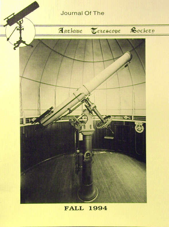
In the fall of 1994 I joined the Antique Telescope Society in their visit to Lick Observatory on Mount Hamilton. In the afternoon we listened to a review of the new book about the history of Lick Observatory given by Mr. Unruh one of the authors. Ref(3) The observatory was in the planning stage even before the University of California existed in the late 1800's. At one time this Mountain on the far frontier boasted the worlds largest telescope, the 36 inch refractor. I had viewed through the 36 inch several times during public viewing years earlier. Venus always appeared to be several images dancing about each other. Since that time the surfaces of the giant Clark refractive lenses had continued to craze and bits of glass were actually falling away. In the early 1990's the 36 inch lens was removed to the University of California Lick Observatory Optical Shop at UC Santa Cruz and there was refigured and tested using modern optical techniques. As the sun set over the hills beyond San Jose I noticed that the inversion layer that had been about 700 feet above the 4200 foot mountain top all day was beginning to settle. As twilight ended the inversion fell below the mountain top and that faint musty exhaust odor was replaced by dry desert air with a slight hint of piney smell. After dark we went to view Saturn through the 36 inch and what a surprise. Saturn shown in the giant eyepiece of the F19 telescope as if a tiny world suspended. The two bright rings were easily separated by the Cassini division and the inner crepe ring was there and the inner edge of the crepe ring terminated at a perfect elliptical edge. As the group of 20 began its second round of viewing I looked up through the slit in the dome an saw the stars begin to twinkle slightly with a bit of breeze. The perfect seeing was over. Looking down at a shallow angle through the inversion layer at the sea of sodium vapor lights of San Jose and Santa Clara the lights seemed to swim. Lick Observatory welcomes visitors on Saturday afternoons to view the exhibits. There is a gift shop run by some of the ladies in the Observatory. The 36 inch is used for public viewing only after several programs given during the summer. The winding road to the observatory is almost always open but the astronomers dislike the reflections of headlights at night. For the amateur astronomer there is Fremont Peak State Park near San Juan Bautista. At Fremont peak there is located a permanent 30 inch reflector dedicated to amateur use. Most moonless weekends during the summer there will be numerous telescopes. Ref(4)
More About Testing At The Eyepiece
and interpretation of diffraction patterns.Telescope testing using diffraction rings is not normally the primary testing method because typical seeing is is too poor to use them repeatably. Ref 'Seeing', Ref 'simulation'
The diameter of the diffraction ring(s) is smaller on larger telescopes so they are rarely seen at best focus with larger telescopes. On observatory size telescopes some light scatter may be present but no rings at best focus. Since rings are actually blurred into spectra the use of monochromatic light improves the visibility. Ref 'Artificial Stars', Ref 'Polishing'Misalignment
Misalignment is usually the easiest problem to correct so we might as well presume that any problem with the telescope is due to misalignment unless we know otherwise. Collimation is covered at alt_21 and collim.htm. The image of a star should be a tiny point at focus and expand to a disk on either side of focus. The disk on either side of focus should look the same. Ref 'Eyepiece Testing' With a telescope that has a secondary mirror the shadow of the diagonal will be seen in the center of the out of focus disk. If the shadow is offset one direction on one side of focus and offset in the other direction on the other side of focus there is a collimation adjustment to be made. Ref 'Polishing' The most perfect star image formed by the primary is formed on its axis and the best part of the eyepiece field is in or near its center. The diagonal is unlike the other optical parts in that it is flat so there is no optical center, only a center of the surface. If the diagonal is minimum size it is possible to offset the diagonal in the tube to avoid cutting off light from the primary. Ref(5) page 327. Ref 'Diagonal Size'
Sometime when the atmosphere is still enough to see the diffraction pattern of a star with a high power eyepiece the collimation may be refined. With the telescope slightly out of focus the central Ary disk will be off of center from the surrounding diffraction rings when collimation is not correct.
Tube Currents
Tube currents might be seen in a large refracting telescope inside a dome. The lens is near to the opening in the dome and radiates infra red heat to the cold sky. The tube of the telescope may yet be warm from daytime temperatures. Air near the top of the tube is cooled and flows down the bottom of the inside of the tube. This would be a laminar flow and not a turbulent flow. Moving the eyepiece inside and outside of focus, on one side of focus the diffraction disk is elongated on one side like an egg. On the other side of focus the same quadrant is flattened. To fix this condition one might mount a small muffin fan inside the tube and run the muffin fan for a while to equalize the temperature in the tube before using the telescope. Popular Schmidt Cassigrain telescopes often have a dew heater near the corrector lens at the top of the scope.
Spider Diffraction
The spider legs support the diagonal in the center of the telescope tube. With the telescope on a bright star lay a broom handle across the top of the tube and defocus the image until the broom handle can be seen against the out of focus disk. Now refocus the telescope and there will be diffraction spikes at a 90 degree angle to the broom handle. Four legged spiders have four diffraction spikes. Three legged spiders have three bright diffraction spikes and three dim diffraction spikes across from the three bright diffraction spikes. Before installing my new diagonal I had a diagonal the thickness of window glass. The old diagonal was rectangular with the corners clipped off with a glass cutter. ( It was also slightly curved causing astigmatism ). With the telescope set up at a school one night we viewed the Moon and Jupiter and the ring nebula in Lyra. Then the students wanted to see what a star looked like so I found Vega expecting some disappointment. Wow!, they said. I looked and saw pointed diffraction lines radiating from a brilliant Vega. There was a slight bit of turbulence that caused spectral color to stream from the star into the pointed prominences. Luckily no one asked me to explain this stellar phenomenon. Moving the telescope to Epsilon Lyrae, the 'double double', the diffraction spikes were too dim to be seen and the double stars could be separated.
Pinched Optics
If a thin 16 inch port hole mirror is supported on a three point mirror cell a distortion can be seen in the diffraction pattern. The diffraction rings that should be circular become somewhat triangular. For more references on the design of mirror cells and an analysis of which type of cell is needed refer to Ref(6). Some of my friends that seem to be knowledgeable have told me that a 16 inch porthole can be supported on a disk of Astroturf.
Spherical Aberration
If the mirror is under corrected, an ellipsoid and not a paraboloid, the light from the edge of the mirror will focus too close to the mirror. Ref(5), page 29. 'Inside of focus most of the light is collected in a strong outer ring, leaving a dim center. Outside of focus the light is driven toward the center surrounded by a ghostly outer fuzziness.' The bright center in the outside of focus case is tempered somewhat by the shadow of the diagonal. Spherical Aberration reduces the performance of the telescope at all spatial frequencies.
Turned Down Edge
For testing cut a round piece of cardboard 1/4 of the mirrors diameter and pin it to the diagonal dowel. Inside of focus the diffraction rings will be of low contrast and fuzzy, outside of focus the rings will be bright and distinct. The turned down edge causes the telescope to perform like a telescope of slightly smaller aperture. The light from the turned edge is usually scattered widely causing a loss of contrast at low spatial frequencies. Masking the turned edge will take care of the scattered light.
Zonal Aberrations
A zone near the center of the mirror is either in the shadow of the diagonal or if outside of the shadow the zone will affect a relatively small surface of the mirror. In the eyepiece test the inner zone shows up more prominently than zones farther out on the mirror. Zonal aberrations require that the eyepiece be thrown further out of focus than required for other defocus tests. A zone on the mirror will appear as a zone in the diffraction pattern. The appearance of the zone in the diffraction pattern may be 20 percent off from the same zone on the mirror due to the bright and dark rings of the diffraction pattern. Throwing the eyepiece farther out of focus will bring the zone nearer to the correct position but may make a slight zone imperceptible. The Ronchi and Foucault test require less skill to obtain the exact location of a mirror zone.
Rough Surface
Testing at the eyepiece the diffraction rings appear to be broken and blotchy. This appearance is very hard to distinguish from turbulence so testing will require a good night. Rough surface can look somewhat like spider diffraction but more broad and less spiky. I suspect my 12 inch mirror has some roughness due to the use of the rose tool. The leaves of the rose tool are narrow and possibly do not smooth the surface enough if not used properly.
Don't Toss that 'Warped' Mirror
The problem may be in your eye or in the alignment of the test setup.Before coming to a conclusion about your optical system check the easy things first. Try rotating the eyepiece in the eyepiece tube to see if the problem rotates with the eyepiece.
I have never seen a permanently warped primary mirror so they must be rather rare but if you suspect the primary try rotating the primary in the mirror cell and readjusting the mirror cell bolts. Make sure the test star is in the center of the eyepiece field.
If you have astigmatism rotation of your eye around the eyepiece axis at the eyepiece can be interesting. The effect of gravity on your eye will cause the aberrations to change at different tilt angles.References
(1) Scientific American, June 1954, page 104
(2) Astronomical Optics, Schroeder Academic Press, Inc.,
also Sky & Telescope, March 1995(3) Eye on the sky: Lick Observatory's first century
(4) Fremont Peak Observatory Association, P. O. Box 1376, San Juan Bautista, CA 95045
(5) Star Testing Astronomical Telescopes Published by Willmann-Bell, Inc.
(6) Sky and Telescope, April 1996, page 76
For a more recent reference see: PLOP Mirror Cell Design.

