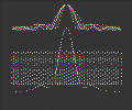
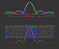
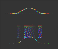
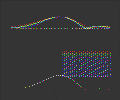
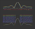
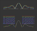
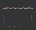
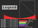
Here are simulated point spread functions generated with the diffraction pattern simulator in the tele DOS or the tel DOS program. A true diffraction pattern spreads the light onto a surface. The calculations done for these simulations are one dimensional. The one dimensional calculations have the same properties as the true calculations. There will be some difference in the light distribution in the true calculation.
Note: The DOS version uses an old video mode. The screens for the Web version were captured using a program called PrintKey. In order to capture the screen for printing if you want to print ronchi patterns made by the DOS program, ron.exe use the program PrintKey.
Unobstructed
Unobstructed
Small Unobstructed Off Axis
IR to
UV
Red to
Blue
Red to
Blue
Red to Blue
Small
Diagonal
Large
Diagonal
Nearly
Pure
Wave Length Legend
Red to
Blue
Red to
Blue
Spatial Frequency
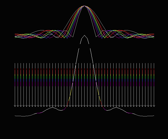
The CCD sees colors that our eyes cannot see. This seems to improve the diffraction pattern.
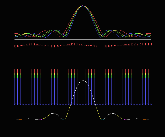
A large refracting telescope. Looking at dim objects our eyes won't see deep red or violet.
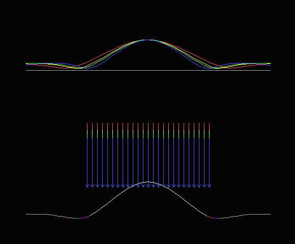
Here is our daytime telescope. Half the aperture, less light and wider diffraction pattern.
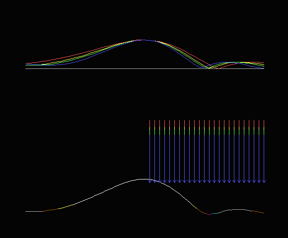
Sometimes when the seeing is bad people mask off a large reflecting telescope to make an off axis telescope. The mask with a circular hole can be aligned to miss the spider supports. This is most likely to help doing planetary work on a telescope with a square diagonal. An off axis diffraction pattern will be more normal on high F number telescopes. Masking won't help on deep sky objects. Our eyes lose the use of cone cells in dim light so any possible gain by masking is lost.
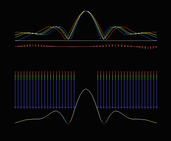
The diagonal will definitely brighten the first diffraction ring. With broad band spectral response the second diffraction ring is blurred but the scattered light is still there.
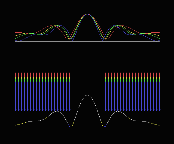
The lost light increases with the square of the diagonal size so those very low F number telescopes fight a losing battle unless the detector is at the prime focus.
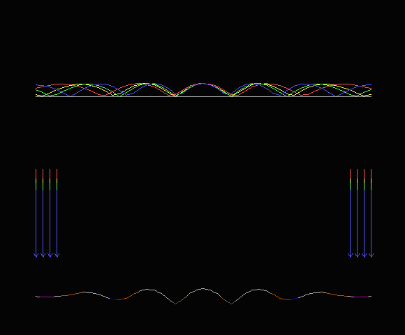
The narrow openings at the edge of the mirror are like two lines of a diffraction grating and produce a 'two slit' interference pattern. If a pure color were used the wave produced would be a sine squared wave across the whole image field. Since we are adding two sine waves of the same frequency why wouldn't the sum be a sine wave? The answer is that the two sine waves are added using 'complex arithmetic' also known as vector addition.

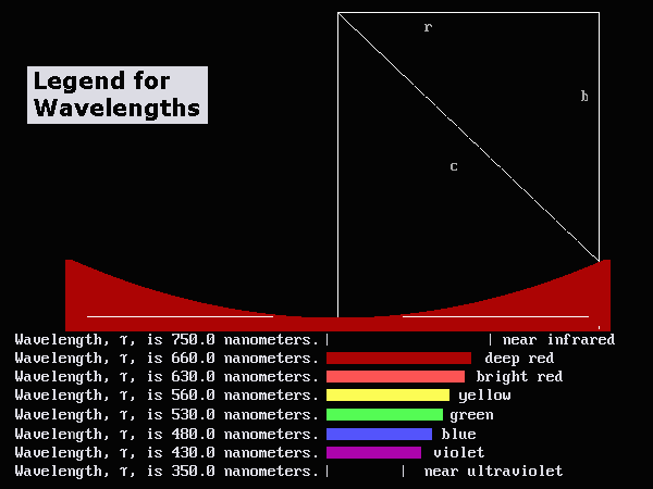
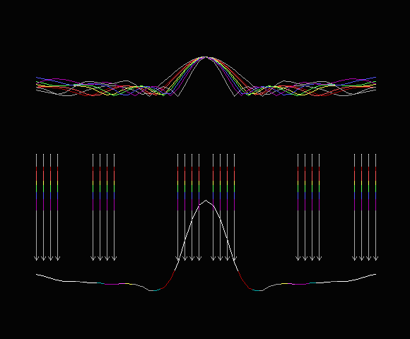
Here is the 15, 70, 95 example from earlier in alt_51.htm.
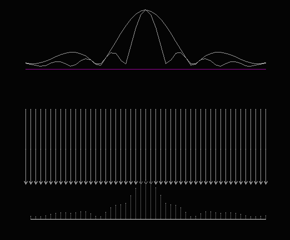
We picked the IR and UV wave lengths only here because of the near two to one ratio of wave length.
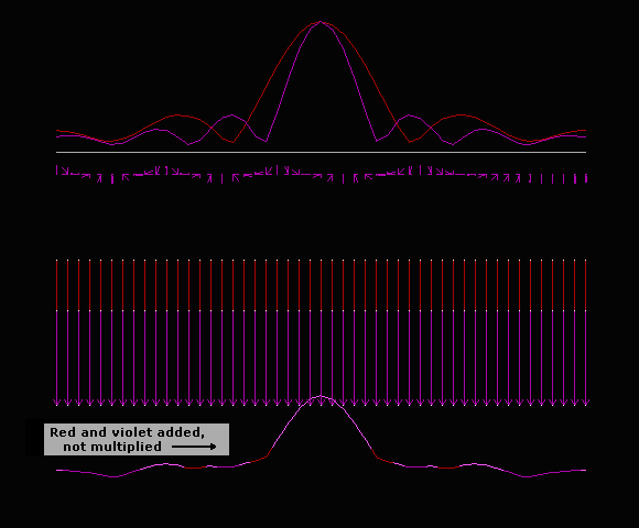
Here is an idea. Illuminate the subject with red and violet only ( 1.5 to 1 ratio ) then multiply the red diffraction pattern by the violet diffraction pattern.
