Table of Contents
Waves
Conic Sections
Waves or Rays
Optics Design Using Rays
Optics Design Using Waves
On Axis Aberrations
Spherical Aberration
Chromatic Aberration
Astigmatism
Off Axis Aberrations
Astigmatism
Coma
Detectors
Our Eyes
Film or Photographic Plate
The Charge Coupled Device (CCD)
The Cassegrain Telescope
The Schmidt Camera and the Maksutov Cassegrain
The Spectrograph and the Diffraction Grating
Seeing through the Atmosphere
The Video Camera
Adaptive Optics
Waves
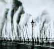
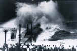
There are waves on the ocean and earthquake waves and sound waves and microwaves and light waves and so on. All waves share certain mathematical properties in common. Not being a mathematician I like to watch waves on water to figure what light waves might do in three dimensions. Waves in a pan will reflect from the edges of the pan. When waves come to a shallow step they will travel more slowly in the shallow. If parallel (collimated) waves come to a step in the pan which is at an angle to the wave front the direction of the wave fronts will be at a different angle after passing into the shallow (refraction).If you tap a coffee mug waves will travel from the rim to the center and on to the rim. In the center of the mug will be a point of maximum wave amplitude (focus). There are two things which we should observe about the coffee waves in our coffee cup which are important to mathematical calculations in optics. 1. Waves leaving the focus will all return to the focus at the same time since all the waves traveled the same distance at the same speed. 2. Wave fronts approaching the focus are circular or in the case of our optics, spherical.
Conic Sections
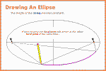
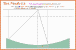
The circle of our coffee cup rim is a member of a family of mathematical curves which include the ellipse the parabola and the hyperbola. If we use a pin and a string to draw a circle we have also drawn a conic section. If we tie a loose string between two pins on our drawing board and pull the string tight with our pencil we can draw an ellipse. If the ellipse were made to be the wall of our wave pan, all the wave would travel the same distance in the same time from the source focus to the other focus. If the foci of our ellipse could be moved a great distance apart and the slack in the string be small compared to the length between the pins we would draw a parabola (well, really still an ellipse but almost a parabola).
Waves or Rays
Before the wave like nature of light began to be understood in the 1800's, mathematicians did optical calculations using rays. Rays pointed the direction the light or wave traveled as the string did in the last paragraph. The rays that mathematicians use for calculation have no width as the string has.Optics Design Using Rays
Designing a telescope the designer usually has some preliminary knowledge of the usual design of the telescope, for instance Newtonian, Cassegrain, Schmidt. If his design is standard he can enter numbers into standard formula for the type of telescope he is building. Maybe the designer is not satisfied with the capabilities of the standard design. Maybe his film is flat and the image field is curved. Maybe stars near the edge of the eyepiece are not points of light. Maybe there is a new type of light detector and the optics of a spectrograph will not bring the light to the detector properly. At this point the design will probably be entered into a computer ray tracing program. The mathematical representation of the optical elements in the computer can be varied and rays used to test the results.Optics Design Using Waves
Optical design using waves could be the design of a spectrograph, the design of a multi layer optical filter or anti reflection coating or the calculation of the minimum possible size of a star image or Ary disk.
On Axis Aberrations
Only one star at a time may occupy the premier position of being pointed at directly by your telescope, all the other stars in the field of view will be off the optical axis of your telescope.Spherical Aberration
Spherical aberration has been reviewed in ALT_13.
Chromatic Aberration
The most simple telescopes using lenses such as the telescope used by Galileo had chromatic aberration. Light travels more slowly through glass than through air or a vacuum. Rays passing through a lens are refracted to a focus. This can be demonstrated in a wave pan by placing a lens shaped shallow below the surface of the pan. Unfortunately for the telescope maker light of different colors (wave length) are refracted to a different degree. As a result of the differences of refraction the image of the star will be separated into colors. Modern lens designers use one or more pairs of lenses to make one or more colors focus perfectly.
Astigmatism
Astigmatism is one of the specifications on my prescription for glasses. If one were to mask our mirror leaving only a north to south band in view and measure the radius of curvature, then mask the mirror again leaving only an east to west band in view and measure the radius of curvature and find a difference between the two measurements one would have found an astigmatic mirror. The focus of an astigmatic mirror will be an east west line at one distance and a north south line at a different distance. An astigmatic lens is said to have a cylindrical component.
Off Axis Aberrations
Astigmatism
The focus of a star which is not on the optical axis will suffer from astigmatism.
Coma
The image of a star in your telescope will look like a little comet with the tail of the comet pointing away from the optical axis. Off axis aberrations for the Newtonian telescope become worse in proportion to one divided by the square of F number. This means that telescopes with low F numbers have lots of off axis aberration.
Detectors
Our Eyes
Our eyes are like little cameras. There is a lens and a screen (retina) onto which an image is formed. There is a stop or iris which adjusts automatically to try to maintain the proper light level on the retina. The retina is not a wide field screen as would seem to be the case. There is only a small area of the image field on the retina which can detect fine detail and which can detect color. Outside of this area which is called the fovea there is a larger area which is more sensitive to light but which can only see black and white light and only in lesser detail. When one is trying to see something very dim it is well to dark adapt which means staying in the dark for 1/2 hour or so to let the retina build up sensitivity. Then for the last bit of sensitivity try to divert your eye slightly from the object of interest. This will allow the image to fall on the area of your retina which is most sensitive. The diameter of the pupil places a restriction on the design of our telescope. Our eye accepts a collimated or slightly diverging beam of light. If the diameter of the light beam is too large some of the light will be lost.
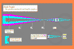
The diameter of the exit pupil equals mirror_diameter in millimeters divided by the magnification. The magnification equals the mirror_focal_length divided by the eyepiece_focal_length. Our pupil at maximum open is only about 7 mm. A 250 mm mirror with a 1000 mm focal length using a 25 mm eyepiece will produce an exit pupil of 6.25 mm. This example is a 10 inch F 4 mirror with a 1 inch eyepiece. If we go to a shorter F number, say F 3.5 or to a lower magnification, longer focal length, eyepiece, say 1.5 inches focal length we will waste our main mirror aperture (diameter). The only advantage that I know of having the exit pupil diameter bigger than the pupil of our eye is that we don't have to hold our head so steady when looking through the telescope.
Film or Photographic Plate
Film has advantages and disadvantages. Unlike our eye, film can store the energy of light over a period of time. This is great since film can easily capture images that are too dim for our eyes to see. Unfortunately during the time exposure the earth is turning. Having a large telescope capable of keeping a star image steady on the photographic plate is not easy and adds another layer of complexity to telescope design. Unlike our eye film has a large area of high resolution. This fact allows the designer into a whole new world of telescope design. For example, the Schmidt camera. Very sensitive film is capable of detecting very dim objects, unfortunately if there is any background sky light from city lights or moon light the film is quickly exposed to it's limit of exposure and the difference of exposure between the object of interest and the exposure of the sky background is lost.
The Charge Coupled Device ( CCD )
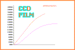
The charge coupled device is a silicon chip. The charge coupled device like film is capable of storing energy, but unlike film the CCD has a large dynamic range meaning that even though the CCD has been exposed to background sky light for a longer time one is still able to measure the difference in brightness between the sky light and the dim object of interest. The CCD is more sensitive to light than film. The disadvantage of the CCD is that it does not have the resolution of film over a large area. CCD's are square or rectangular arrays of light sensitive pixels. A 1 inch by 1 inch CCD might have 1000 pixels on a side making an area of 1000000 pixels. This seem to be plenty of pixels but using film one can fill a square 6" by 6" or larger with detail that may only be observed with a microscope.
The Cassegrain Telescope
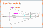
The Newtonian telescope has two mirrors but the diagonal has no power, meaning that it is flat and is only used to redirect the light to a more convenient viewing place. The Cassegrain telescope has two mirrors which share the power so to speak. The Cassegrain telescope can be made much shorter than the Newtonian telescope. For small telescopes this makes a very portable telescope but a telescope which has no optical advantage for the amateur astronomer and costs more to build. For observatory telescopes with very large main mirrors the main mirror must have an F number in the F3 to F5 range in order to fit the telescope into the dome. The other advantage for the observatory telescope is that different secondary with different power may be installed. The Cassegrain primary or first mirror redirects the light to the secondary mirror which redirects the light again through a hole in the primary mirror to the focus. To form a focus it is necessary that the waves of light approaching the focus be spherical. There are a family of primary and secondary mirror curves which can meet this requirement. Beyond this if one would like one may add correcting lenses before the focus to allow an even greater choice of primary and secondary curves. Since the shadow of the secondary mirror falls in the center of the primary mirror one would prefer that the secondary mirror not be too large. The classical Cassegrain telescope has a paraboloid primary mirror and a convex hyperbolic secondary mirror to redirect the light to a focus more distant from the primary in terms of light path length. The effect of the convex secondary is to increase the F number and the magnification. The convex hyperboloid secondary mirror accepts the spherical wave fronts from the primary mirror and reflects the light to form spherical wave fronts of lesser curvature. If one wanted to build a Cassegrain telescope one already knows how to make the primary mirror so one would build the telescope with the primary mirror and then using a distant collimated light source grind and polish the secondary mirror to form the perfect focus. Calculation of off axis aberrations take on a new complexity in the Cassegrain telescope since the converging wave fronts from the primary mirror do not fall directly centered on the optical axis of the secondary. As calculations become more and more complex at some point the optical designer/ mathematician must become an optical designer/mathematician/ computer programmer. Thousands of curves are simulated in the computer and rays are traced through them. The computer is programmed to search for a set of mirror curves which best satisfy the optical designers plans. The Ritchey-Chretien telescope is a two mirror Cassegrain telescope which has been optimized. Both mirrors in the Ritchey-Chretien are conic section curves. The following specification is taken from 'Astronomical Optics' by Daniel J. Schroeder. In order to specify the radius of curvature of the zones of our Ritchey-Chretien telescope mirrors we will use the variable K. The conic_constant, K can be plugged into the following formula from page 38 of 'Astronomical Optics' to find the zone_radius_of_curvature.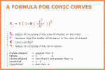 In sentence form the formula is zone radius of curvature
equals radius of curvature of the center of the mirror times
the following quantity: The radius on the mirror of the zone
of interest squared divided by the radius of curvature of the
center of the mirror squared times the conic_constant, K then
subtracted from one and raised to the 3/2 power.
Various values of K produce the following conic curves:
	    Prolate ellipsoid     K greater than 0
	    Sphere                    K =            0
	    Oblate ellipsoid      K less than 0 and greater than -1
	    Paraboloid              K =           -1
	    Hyperboloid           K less than   -1
In the classical Cassegrain primary K is -1 for a paraboloid. In one design for a Ritchey-Chretien primary K is -1.0417.
The Schmidt Camera and the Maksutov Cassegrain
The two main telescopes on Mount Palomar are the 200 inch Hale Telescope and the 48 inch Schmidt Camera. The Schmidt Camera was designed to survey the entire sky visible from the latitude of Mount Palomar. By surveying the sky over a period of years a record is made of the relative motions of the stars. More recently the 48 inch Schmidt has been used for finding and tracking asteroids with orbits that cross the orbit of the earth. The single mirror of the Schmidt camera is spherical. A sphere has no optical axis, only a center so an off axis star in the Schmidt is only off axis relative to the telescope tube. The photographic plate is placed near to where the focus would be if a paraboloid mirror were used. Now we have a camera which has spherical aberration but no coma or astigmatism and the spherical aberration is the same for every star in the field. Is there some place that we can place a correcting glass to correct the spherical aberration for every star in the field? The answer is that we can place a stop and a correcting plate at the center of the sphere.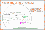
The correcting plate is flat on one side and has a surface on the other side that has the refractive power to reproduce the difference between a sphere and a paraboloid relative to the 70% zone. The reason for not making the correcting plate relative to the edge or center is that by making the correcting plate relative to the 70% zone we reduce the maximum refractive power required. By reducing the maximum refractive power required we reduce the chromatic aberration of the correcting plate. The correcting plate is a surface of revolution about its center. There is a hill in the center. The surface of the 70% zone is parallel to the flat back surface thereby having no power and the surface rises to the edge. There are a series of articles about the Schmidt Camera in 'Amateur Telescope Making' book three, Scientific American. The Maksutov Cassegrain is similar to the Schmidt. The Maksutov Cassegrain is a very compact and portable telescope but of greater cost. In place of the correcting plate in the Schmidt a meniscus lens is used. A meniscus lens is convex on one side and concave on the other, having the general shape of a dish. The convex surface is toward the main mirror. The center of the convex surface is aluminum coated to provide the Cassegrain secondary. The concave surface of the meniscus lens is corrected to provide a near perfect focus at the Cassegrain focus.
The Spectrograph and The Diffraction Grating
The spectrograph divides the colors of a star into the rainbow colors. It is found that different atoms and molecules emit light of very specific colors when excited or heated to various temperatures. In addition the speed of the atoms in a distant star cause a Doppler shift in wave length or frequency in cycles (waves) per second of the observed specific colors or spectral lines. The speed of the atoms toward or away from us which is measured by Doppler shift is called radial speed or radial motion.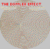 Looking at a double star system such as Epsilon Lyrae
and using the relative motions from the Schmidt camera to
determine the distance by parallax and obtaining the radial
velocity from the spectrograph it is possible to determine
the orbital elements of the double star system and the
masses of the stars. Measuring the spectral lines of the
stars we can determine the type of stars and the stars
life times and many other things.
The heart of the spectrograph is the diffraction
grating. The diffraction grating in a professional
spectrograph is a flat piece of glass which has had
tiny lines scraped into it. The grating is then coated
to make it reflective. To understand a diffraction grating
it is necessary to use calculations which involve the
wave nature of light. If we shine a collimated beam of
light directly at the grating most of the white light
is reflected back. However some of the light is reflected
from the tiny scraped lines and spreads into a narrow fan of cylindrical spherical
wave fronts from each grating line. If we pick a single ray in the fan of light
from one grating line and a parallel ray from the fan of
light from an adjacent grating line we will find that light
of only one wave length will be in phase when the waves
in the two parallel rays are compared. The tiny wavelets
from each grating line combine to form wave fronts departing
from the grating at a particular angle. The angle of
the departing wave fronts depend on the wave length of the
light we shine on the grating. A demonstration of the
diffraction grating can be done in a pan of water using
water waves.
 In simplified terms the rest of the spectrograph
consists of a collimating lens to turn the diverging
wave fronts from the main telescope focus into straight
wave fronts for the diffraction grating and a camera
to capture the parallel wave fronts coming from the
grating and focus them onto the film or CCD.
Seeing through the Atmosphere
'Seeing' is the term used to describe the steadiness or lack of twinkle of the stars. Good seeing will allow us to use more magnification on our telescopes. Bad seeing will allow the average telescope to appear to be just as good as the best. Problems with seeing can be grouped into several types. Starting at the telescope there is usually some turbulence in the telescope. Refer to alt_51.htm for information about turbulence in the telescope. Next there are heated houses or the warm engines of cars and stone fences which make turbulence. Above this if the wind is blowing there will be air near the ground that is slowed by stationary objects on the ground such as trees causing a wind shear. If you are in a valley near the coast there will be cooled air from the water below warmer air above to cause uneven refraction within a few hundreds of feet of the ground. Looking through turbulent air near a thunder storm or through a jet stream can cause fast turbulence. The image of Jupiter's moons may jitter so fast that it appears the telescope is out of focus. Often nights that are hazy and quiet can unexpectedly have exceptional seeing. Below are two methods that can be used to improve seeing on good nights.
The Video Camera
Modern video cameras can be quite sensitive. Making a video of something very bright like the moon one can use a stop motion sports camera with a very short exposure. Thousands of exposures are recorded on a video replay disk. Then it is just a matter of going through the pictures one by one to find that one in a thousand shot when the atmosphere was just right.
Adaptive Optics
Adaptive optics technology arrived sometime before the 'star wars' era of the 1980's. The original function had something to do with identifying unknown satellites. The technology has become fully available to astronomers since the early 1990's. Adaptive optics takes the active approach to seeing through the atmosphere. Mirrors move to correct aberrations ten times faster than turbulence can produce them. Making these correction can be done but its not cheap. Not within the budget of most amateurs.
To make a correction one must first know which direction to correct. One thing we know for sure is that before the light from a distant star entered the atmosphere the wave fronts were perfectly flat. Is there anything remaining of that flat wave when the light reaches the ground? The presumption used in adaptive optics is that if the seeing is good there are patches of flat wave front across the aperture of our telescope mirror. If we use a mirror made of many small mirror we can make the patches of flat wave front parallel to each other correcting the wave front waviness.
At right is a diagram showing a device that detects wave front distortion. It is an array of tiny lenses in the unfocused light from the telescope. Below each lens is a field of CCD pixels to detect wave front distortion. The signal from the wave front detector is sent to a 'rubber' mirror. The mirror surface is very thin and below the surface is an array of tiny piezo electric actuators. By applying high voltage across the piezo electric actuator crystals the 'rubber' mirror can be deformed.
The wave front detector has a problem in that it is not at the focus of the telescope. The light from the star was very bright but now we have divided that light between hundreds of detectors. Although the system will work on bright stars there are far too few bright stars available in areas of the sky where astronomers want to look. The next development in adaptive optics was the artificial star.
Attaching a very powerful laser to the telescope it is possible to create an artificial star at any desired location.
The artificial star although very distant and small may jiggle when viewed against the background stars. For this reason and for other reasons it is necessary to have a second flat compensating mirror to remove motions from the entire field of stars for the final CCD data camera.
An initially unforeseen benefit of adaptive optics is that aberrations such as astigmatism in the original telescope will be corrected by the adaptive optics system if the aberrations are 'inside the loop' of the adaptive optics system.
Adaptive optics systems can easily improve the typical amateur telescope resolution of 2 arc seconds to .02 arc seconds. There has been even greater improvement with advanced systems this millennium. Not only resolution has benefited but also sensitivity by concentrating the scattered light of a star that previously fell onto many CCD pixel onto one or two pixels. Stars that were previously undetectable have become visible. The 80 year old 100 inch at Mt. Wilson has benefited greatly from the CCD and then from adaptive optics. At the Keck Telescope in Hawaii adaptive optics has allowed the resolution of stars in orbit around the black hole at the center of our Milky Way galaxy. All designs for future observatory telescopes now include adaptive optics.
