
Mirror testing at the Telescope Makers Workshop
|
|
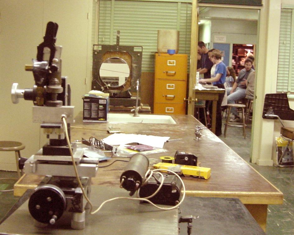
Here is the mirror testing set at the telescope makers workshop. The mirror is on an adjustable platform to allow for easy adjustment. A small bungee holds the mirror. |
|
|
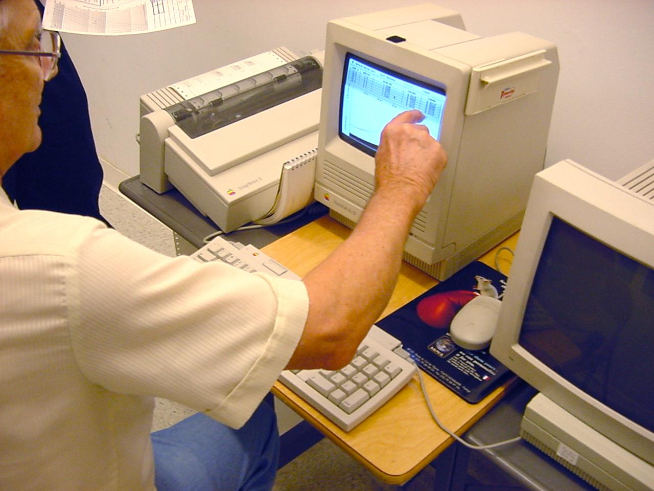
After measuring the focal length the mirror parameters have been entered into a computer program to generate a simulated ronchi-gram. Always using the same setup with the grating inside of focus allows us to become experienced at reading mirrors. Normally the computer printout would have a dark line in the center with a white line on each side. During mirror testing moving the grating left or right causes the lines to zip by at lightning speed. |
|
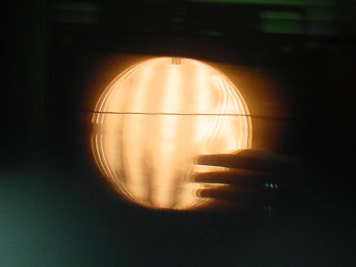
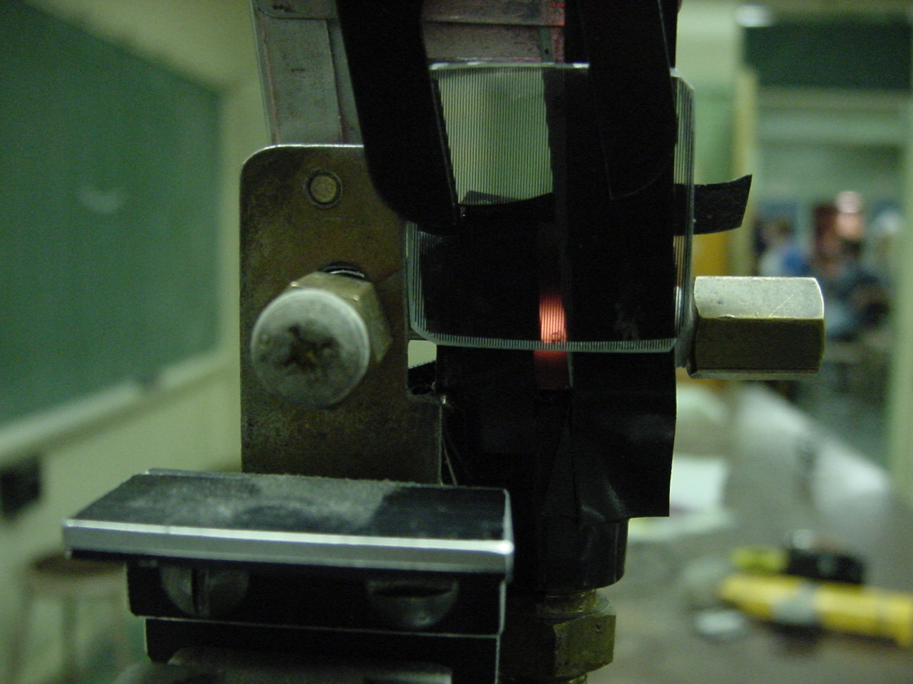
In this setup the same grating produces both the slit and the filter for light returning from the mirror. A small flashlight bulb with a dimmer is behind the grating and three slits are actually produced due to the size of the light bulb. The three slits cause no problems while visually testing but seem to cause a triple image when using the camera. All the picture below have this triple image effect to some degree. |
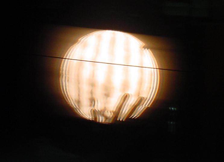
Here are the ronchi-grams that we compare to the computer simulation. The mirror has a turned down edge at the outer 1/4 inch of aperture. Try to look for this in the ronchi-grams.
 |
 |
 |
| 12 o'clock | 1:30 | 3:00 o'clock |
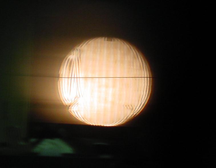
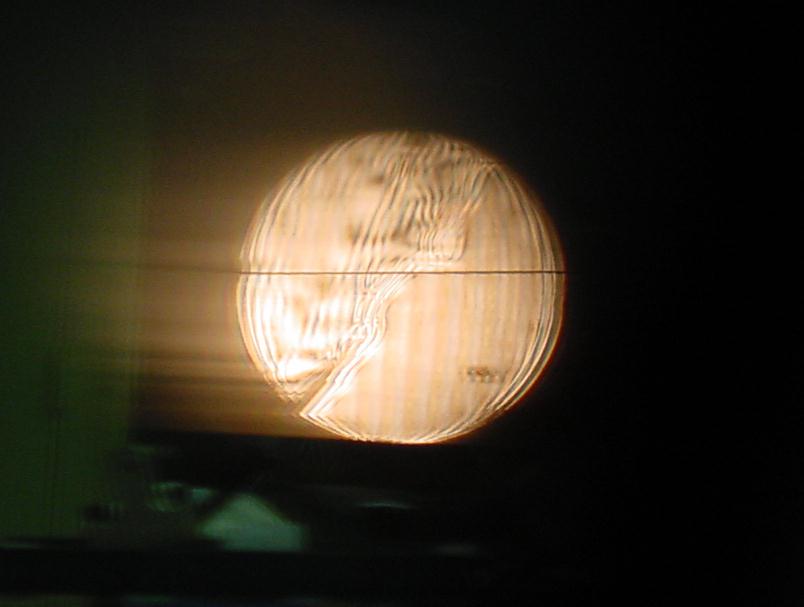
Here the grating is further inside of focus. The test becomes less sensitive further inside of focus. Too bad the triple image effect washes out the contrast. To keep from becoming confused we usually test inside of focus. One exception is when trying to detect a turned down edge. Outside of focus the lines would spread rather than shrink at the mirror edge. For some reason testing for turned edge outside of focus seems to be more sensitive.
 |
 |
 |
| 12 o'clock | 1:30 | 3:00 o'clock |
The Knife Edge Test Equipment
 |
The knife edge setup is an adaptation of a set described in Sky and Telescope. This set is extremely sensitive and relatively easy to use. When the article was written bright LED's were not available. |
 |
Here we test my 12 1/2 inch mirror after I attempted to reduce the turned edge by polishing just inside the edge. The zonal polishing didn't reduce the 1/4 inch wide turned edge by much but made quite a zone on the mirror. The knife edge would be on the right side and the imagined rising sun shinning from the left. Think of the rising sun lighting the sharply turned left edge. The knife edge is closer to the mirror than the focal plane of the mirror edge. |
 |
Design for a home built Ronchi / Foucault Tester |
The Final Mirror Testing
Experimenting with heat effects
Experimenting with mirror warping
A spherical mirror can be warped to be a parabola using a special harness. Also sometimes the corners of square mirrors are warped slightly to bring them into tolerance. In this case we are starting with a reasonably good mirror and warping it out of shape to see what happens to the ronchi lines. Our harness lifts at two points at the edge of the back and presses down with a compressed spring in the center of the mirror face. We used foam tape to keep the spring from damaging the glass.
Here the spring pressed down 20 pounds in the center and lifts up 10 pounds at two points on the back edge. The mirror only weighs 20 pounds so its hard to imagine a mirror cell that would support the mirror this poorly.
 |
 |
 |
| 20 pounds 12 o'clock | 20 pounds 1:30 | 20 pounds 3 o'clock |
Here I further compress the spring to produce 40 pounds pressure at the center and 20 pounds lift at each edge. With this much warping force I was beginning to have a bit of panic attack. At 12 o'clock the turned down edge has become a turned up edge. Amazingly with the harness at 3 o'clock you can hardly see a thing. This much astigmatism would show up easily in an eyepiece test. If you are doing your final testing using the ronchi test you should be careful to maintain mirror symmetry otherwise you might miss astigmatism during the ronchi test.
 |
 |
 |
| 40 pounds 12 o'clock | 40 pounds 1:30 | 40 pounds 3 o'clock |