Later we will try to get the friction of the base bearing to be about the same as that of the altitude bearing.
There are many ways to make the altitude bearing. We want the bearing to be stiff enough that the telescope won't teeter totter when we change the eyepiece. At the star party we will be guiding the telescope after every third person so we don't need a bearing lock. Some people add a screen door spring from the center of the bearing to the base to increase the friction.
|
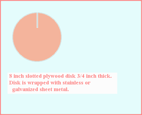
Here is a design that will work for most Dobsonians. We cut a plywood disk 8 inches in diameter from 3/4 inch plywood and slit it with the saw. From the sheet metal shop we find some scrap sheet metal less than 3/4 inch wide and wrap it around the disk and into the slot. Stainless would be nice but galvanized will do. Careful of that sharp edge on the sheet metal. Dull the sheet metal edge with sandpaper. For more about this type of bearing see 8_inch-a.htm. |
|
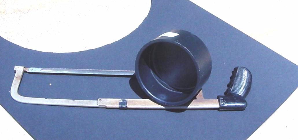
We found this 4 inch plastic pipe cap at the hardware store. It is almost 5 inches on the outside. Two of these would work for the side bearings on a small telescope. |
|
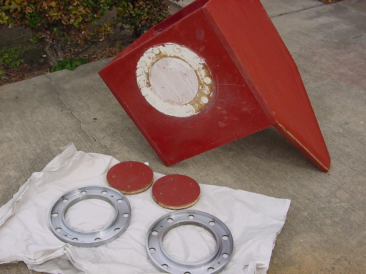
We found these 9 inch OD pipe flanges at the junk yard. They worked well for years but eventually the telescope got too heavy for us and we had them machined down. They are still much stronger the necessary. |
|
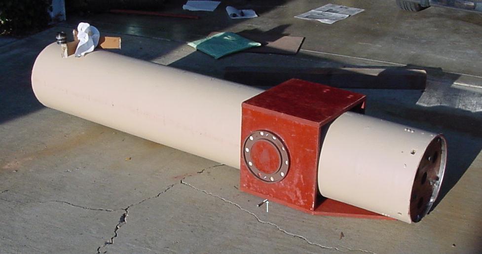
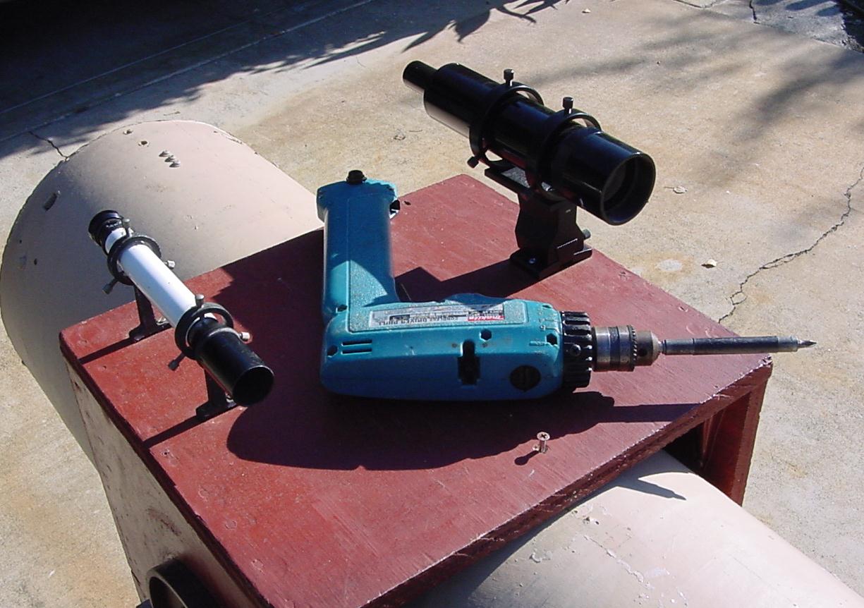
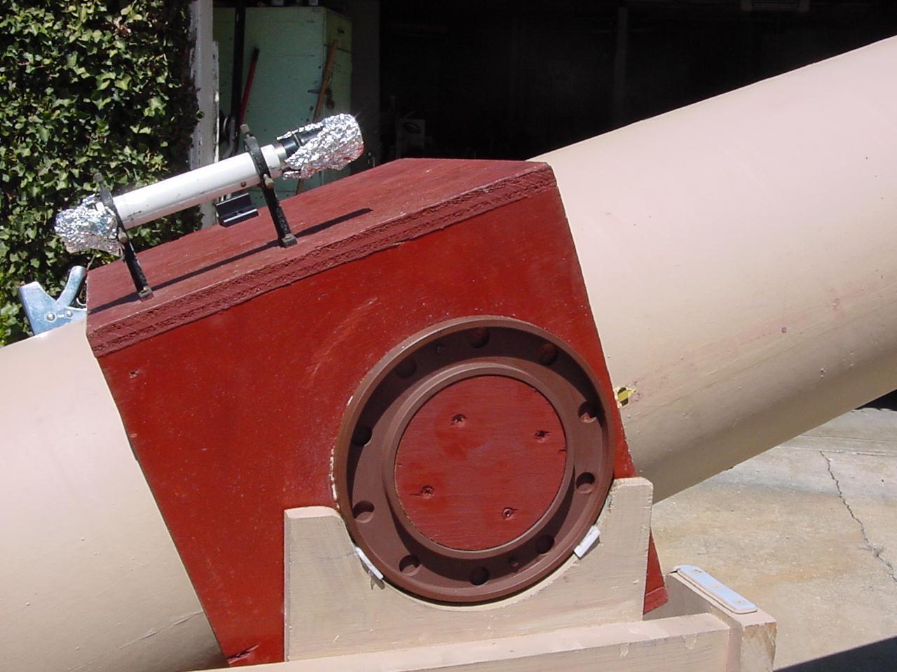
We make the tube box 1/8 inch oversize so we can slip the tube through the box for fine adjustments later. The tube box is roughly a hollow cube made of 3/4 inch plywood. The altitude bearings must be mounted near the eyepiece end of the tube box. If the altitude bearings were centered in the sides of the tube box the box would hit the web of the base structure when the tube is tilted down. In this picture we have placed a bolt on the ground below the bearing center as a balance point. To find the final balance point we have placed the diagonal and eyepiece assembly in the tube. We slide the tube through the box until the tube is balanced. |
|
We need to know where the tube box will be on the telescope tube so we will know where to mount the cradle boards and how tall to make the base structure. One deck screw in the center tacks the tube box to the tube temporarily. Then we measure from the surface of the bearing to the ground at the mirror end of the tube and add an inch for later adjustments and we have the height of the cradle above the top of the rotating base. To build the base we also need to know the space between the sides of the base. |
|
Here we see how the Teflon pads will be screwed or nailed to the cradle boards with tiny finishing nails. If Teflon is not available there are slip pads made for use under furniture at the hardware store. The Teflon pads overhang on the inside about 1/16 inch to keep the tube box from scraping on the cradle boards. When deciding the distance between the inside of the base structure we add 3/16 inch for clearance. Since you have already built the tube box add the tube box width to the 3/16 inch clearance plus twice the thickness of the cradle board plywood to find the space between the base structure sides. Now knowing the space between the sides of the structure we can decide the size of the fixed and rotating base and cut them from plywood. |
|
We
decided we wanted the tube to tip down to horizontal so we "V"ed
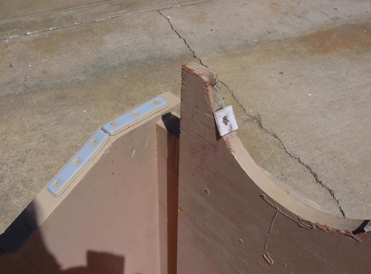
the web of the structure. After building the structure on the rotating
base we can tack the cradle
boards to the base structure with deck screws and test the clearances with
the rotating base and the web. When we are
done we can fill any extra screw holes with latex caulk.
Later we will try to get the friction of the base bearing to be about the same as that of the altitude bearing. |