The purpose of the nine point mirror cell is to divide the weight of the mirror equally over nine points. The points of support are chosen to produce the least possible bending of the mirror glass. This mirror cell would be used with a one inch thick, 12 1/2 inch diameter mirror. The 2 1/4 inch thick mirror shown in the photographs was used because a thin mirror was not available. Mr. Dobson has made many mirror cells for thin mirrors and I suspect this design would be considered overly 'high tech' by him. If you can afford to have a small bit of sheet metal work and machining done for you and you have some wood working tools this design should be fine. To test a thin mirror precisely it needs to be tested in its mirror cell.
|
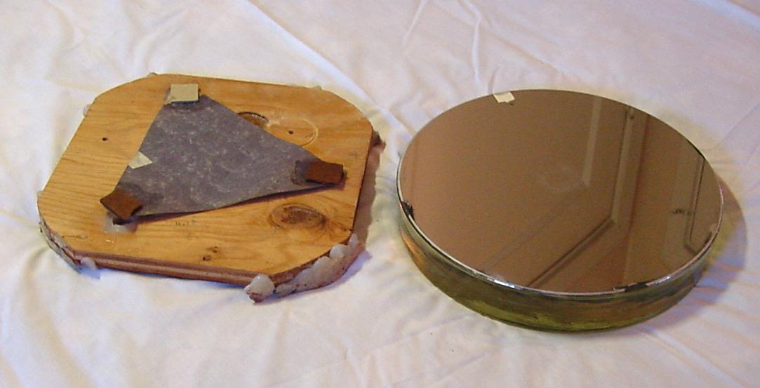
Here is the original cell which served well for 30 years. Three chips of masonite are glued to a piece of cardboard. The center of the cardboard is glued to the plywood to hold it in position. Three half inch bolts are threaded through the plywood for tilting the mirror. The mirror edge rests on three blocks of wood screwed to the side of the cardboard tube. The mirror is kept from falling forward by three furring nails. Furring nails have cardboard bumpers for padding. |
|
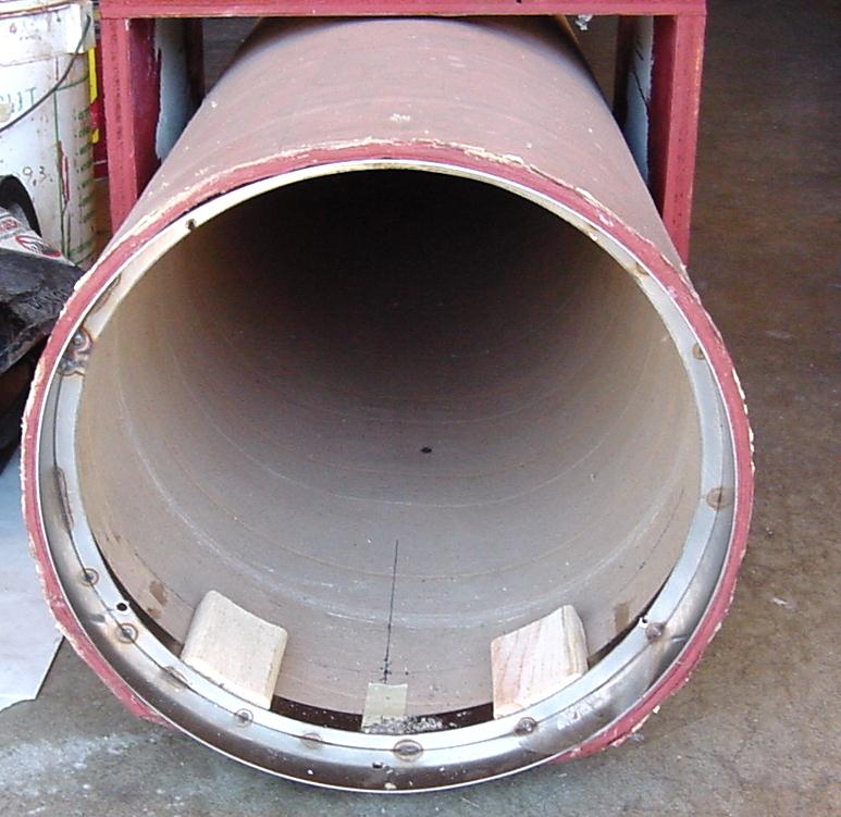
We considered replacing the cardboard tube but it still seemed to be sturdy even after 30 years. We had a stainless cylinder rolled by a sheet metal shop that would just slip into the cardboard tube. Galvanized sheet metal would have been cheaper and easier to work. A ring has been welded inside the cylinder to provide an attachment for the mirror cell. We used an electric belt sander to shape two hard blocks of pine to the curve of the tube on the outside and to the curve of the mirror on the inside. |
|
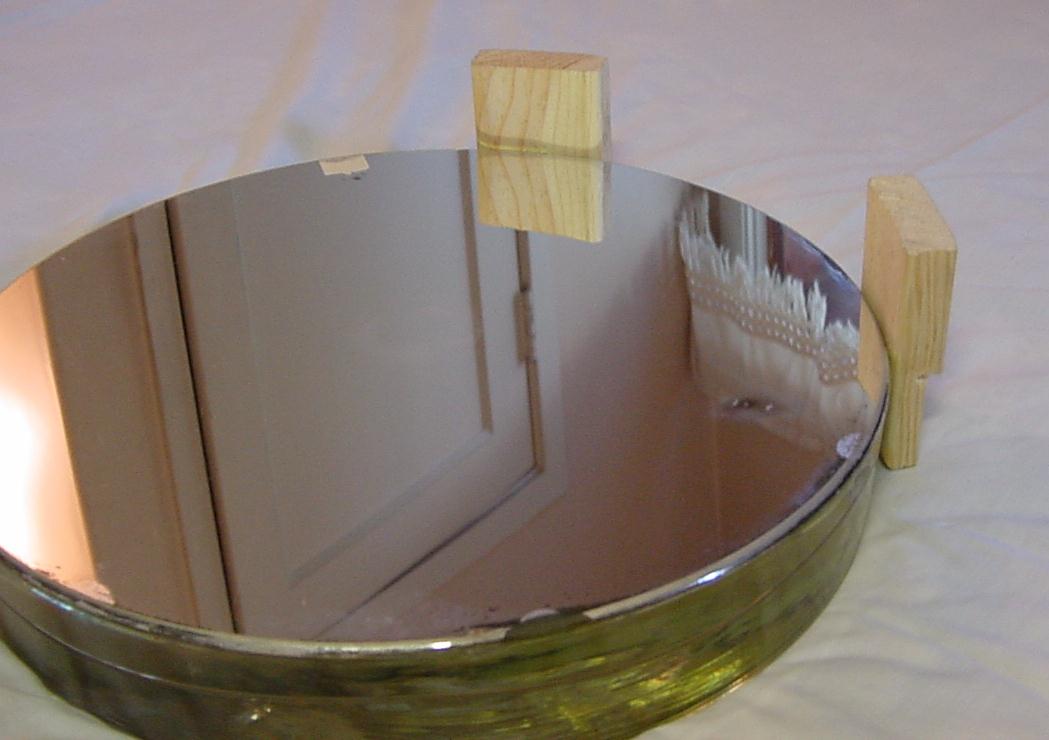
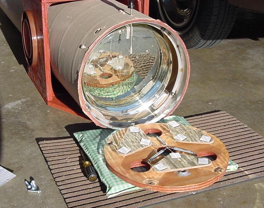
Here we test the curve of the pine blocks to the mirror. The mirror coating is over 10 years old and has hardened. It is standing up well to my handling. |
|
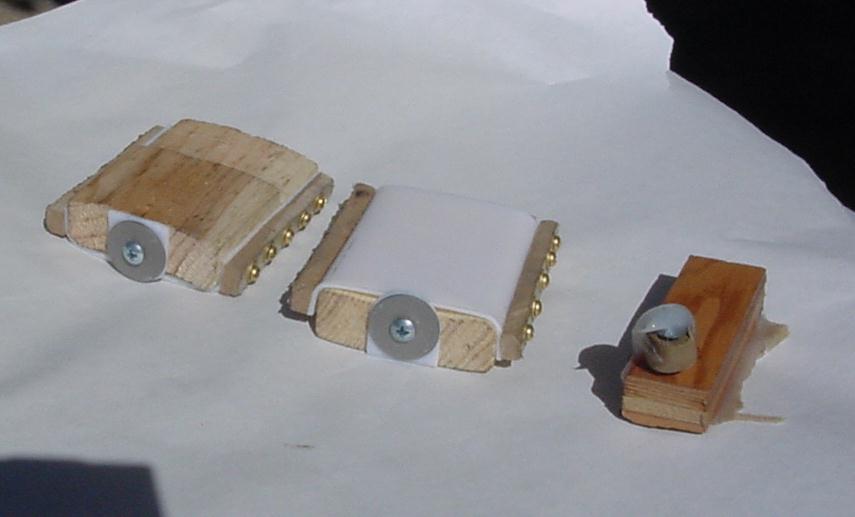
Since we are going the fancy route we add 1/16 Teflon sheets to our pine blocks. The 20 pound weight of the mirror is insufficient to completely compress the Teflon against the pine blocks. This adds a bit of cushion when riding in the back of the truck. When testing the telescope at low elevation angles we add a bit of masking tape over the Teflon to keep the mirror from slipping away from the nine point flotation. |
|
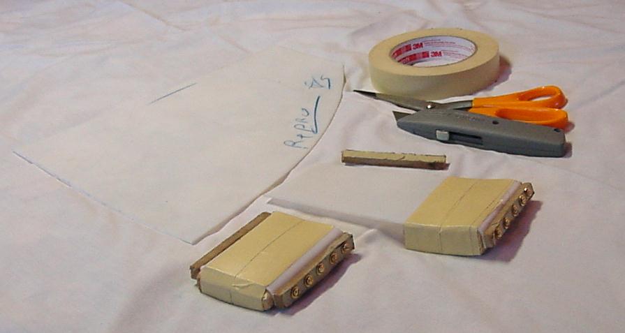
Here are the completed mirror edge blocks. We padded the steel washers with Teflon. The original block with furring nail seemed OK for the top block. When riding in the truck the bottom of the mirror slides forward against the washers. You don't want the mirror to jump over the washers on a bump in the road. Adjust the top block for a small clearance and don't transport the telescope with the mirror cell adjustment bolts screwed all the way out. |
|
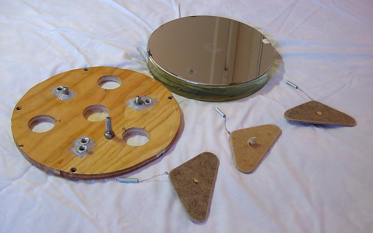
We have chiseled out one layer of plywood and glued in 1/2 inch nuts with Silastic sealant. We tightened the bolt to hold the nut while it dried over night.. There is an extra set of nuts because we were originally planning a three point cell. We will use the inner set of nuts for the nine point cell. We scaled from drawing 4A for the location of the nuts but the precise location is not critical. The bolts are soft steel. A machinist chucked them in a lath and bored a 10 32 tap hole down the center of them. The bolts were cup shaped on the end. We ground them slightly convex then taped them. |
|
We laid out the flotation triangles on the back of the cell to check the measurements before cutting the triangles from masonite. We rounded the triangle corners with the belt sander. The triangles are attached to the end of the bolt with small flat head 10 32 screws. We glued the treads so they can be left slightly loose to allow the triangles to rock. The triangle alignment springs are attached with small wire and tiny screw eyes. |
|
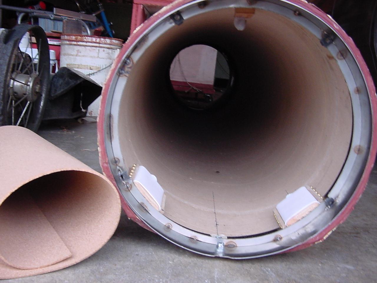
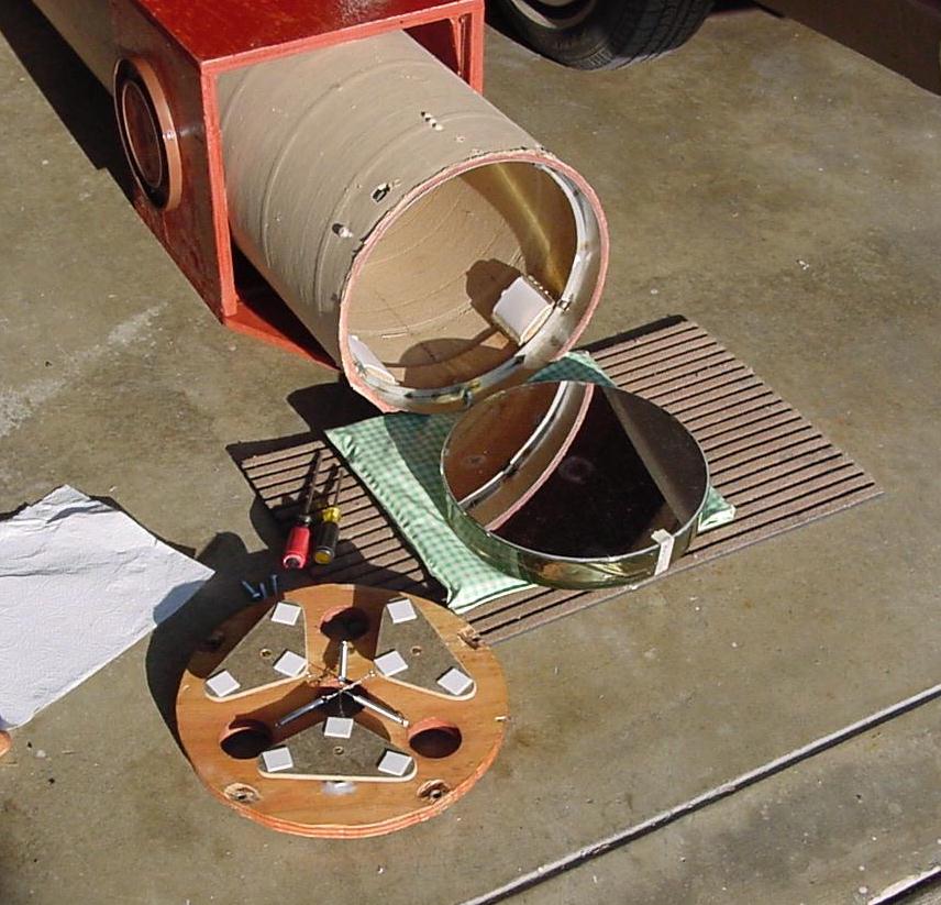
We covered the metal near the mirror face with cork to reduce the heat waves. Had the entire tube been metal the entire inside of the tube would have needed to be lined with cork. We installed four 1/4 inch clip nuts on the sheet metal ring to hold the mirror cell. To do this we cut through the tube cardboard to the metal cylinder then removed the metal cylinder and ground a bit away to allow the clip nuts to slip on the edge of the metal ring. During mirror installation the clip nuts need to be pushed out a bit to clear the mirror. We reinforced the mirror cell plywood with 5/16 anchor nuts glued into place since the mirror will be removed many times during testing. |
|
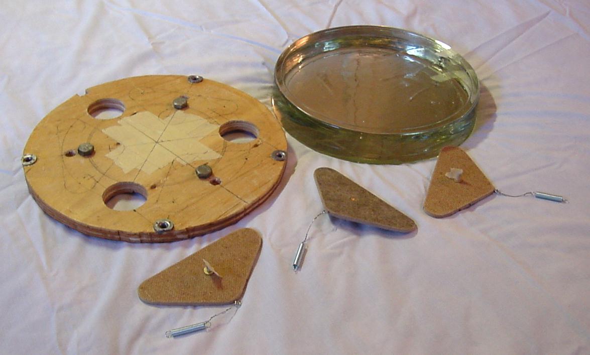
We used foam mounting tape at the ends of the triangles to rest on the mirror. We left the slippery backing on the tape. Normally we don't stick tape to the mirror face as show here. We did this to test the effect of the tape on the mirror coating. |
|
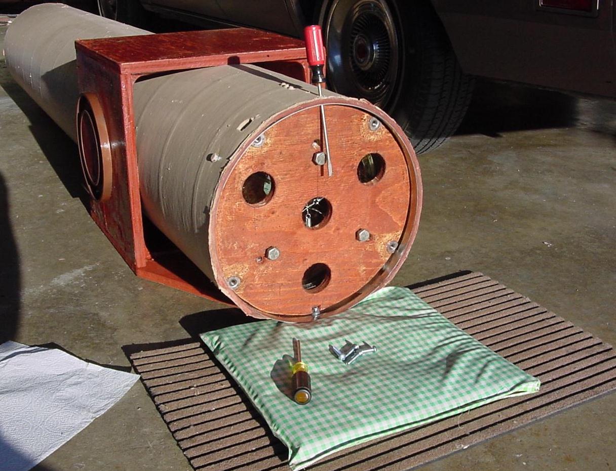
There is an unused hole in the top of the tube that we can slip a screwdriver through. There is an indexing nut in the bottom of the tube to index the bottom of the mirror cell. The mirror cell may need to be spaced off the ring during testing on stars closer than infinity. See three-dist. I have used four small one inch long pipe nipples for spacing during testing. Extra long 1/4 inch screws help to assemble for testing. |
|
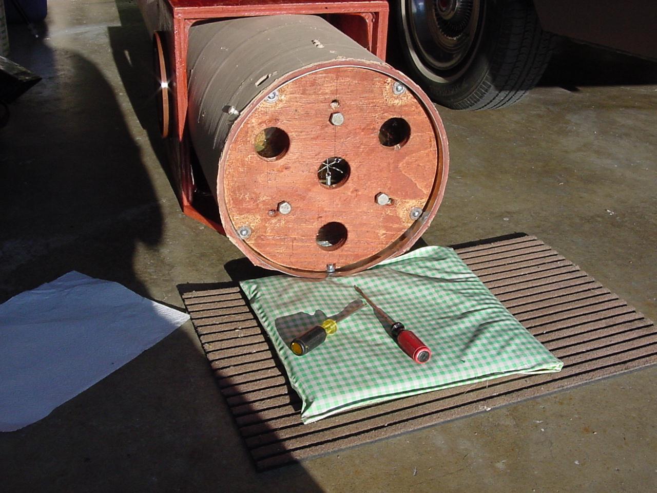
We push in the clip nuts and install the four screws. We have replaced the lower part of the tube box with a new piece of plywood to extend under the mirror cell. This probably wasn't necessary unless we are worried about 30 years from now. |
|
Now its together. We slide the tube inside the tube box a bit to rebalance the tube. It works great. If this were new construction we would now install the spider and eyepiece temporarily and balance the tube box on a pencil. Once we know the location of the pipe flange bearings we can install the cradle boards on the rotating structure. |
|
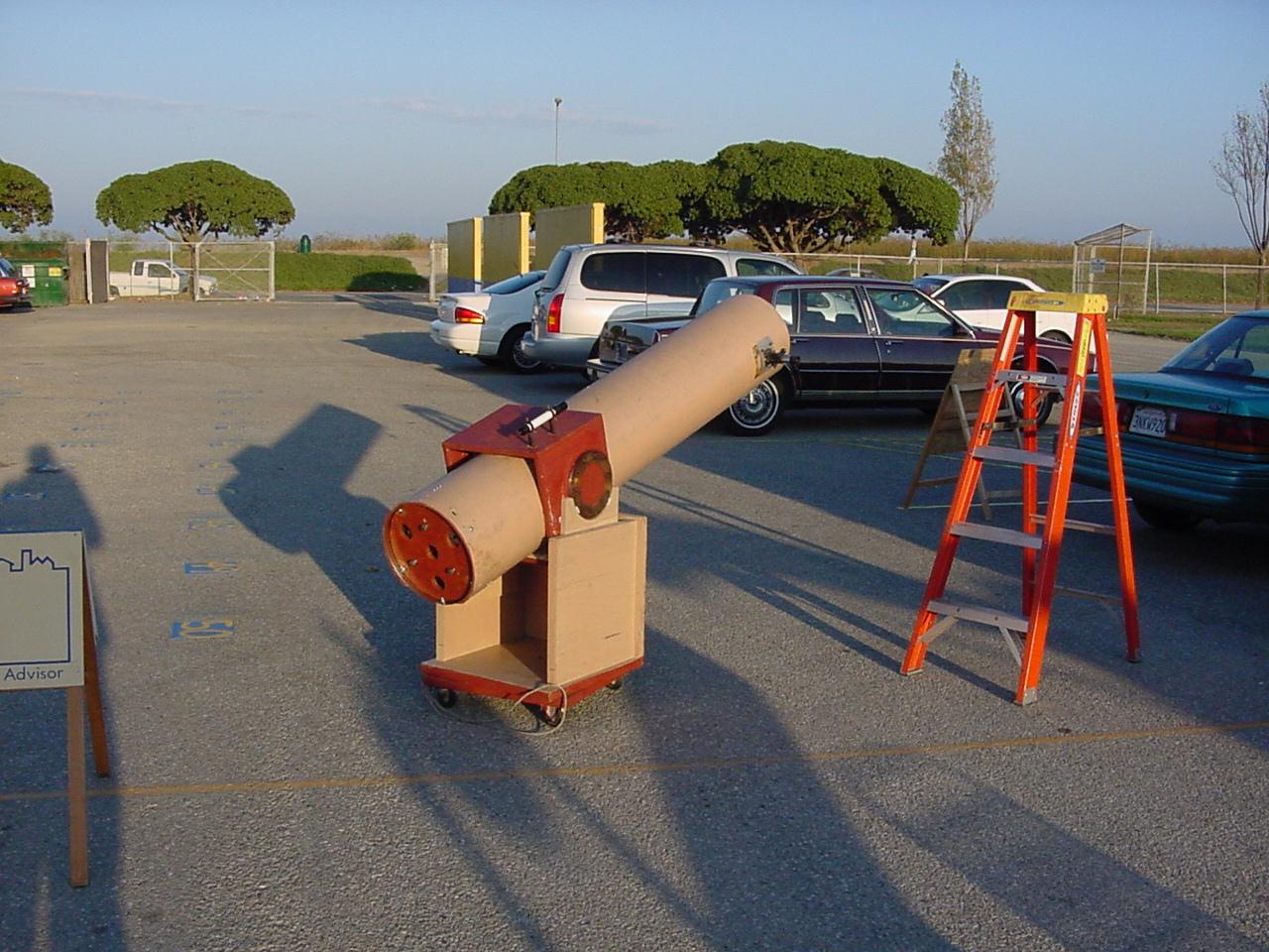
Here we are at Astronomy Day in the fall of 2000. Since we plan to do some photography with our digital camera the next project will be a rework of the eyepiece. |
|
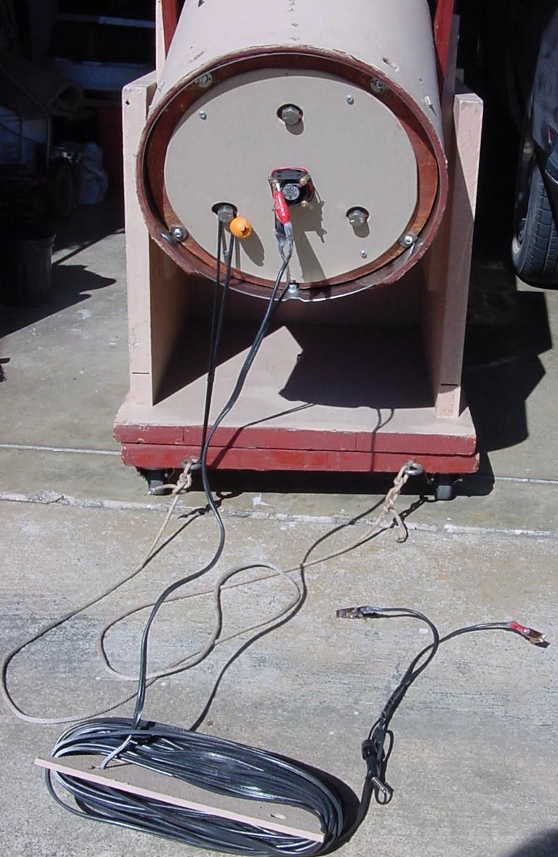
Since Astronomy Day we have added a small 12 VDC exhaust fan to the mirror cell. The fan is intended to shorten the cool down time for the telescope. The small inexpensive fan is made for cooling a computer chip inside a computer. It runs fine off a car battery. At this time the consensus seems to be that the fan should blow across the mirror face. I decided that I didn't want to add a fan to the side of the tube. I would say that the fan is very optional. At school star parties the wire makes a tripping hazard in the dark. The bungee balances the tube cover during storage. |