Generating spherical curves in glass
Background
One of the more tedious operations in making telescope optics is rough grinding. Loose abrasive and water are ground between two disks of glass, and due to differential pressures, the top disk will become concave, and the bottom convex. This is simple enough in theory, but in practice it can take hours of work to generate even shallow curves. Other ATM's have resorted to using cast iron rings, and even cat food cans to speed up the roughing process.
For AA-SPIT, there are five strong curves (one surface is flat), and five matching tools to make. In the optics industry, there aren't enough cats to feed all the excess cat food, so they use diamond cup grinding wheels instead. I purchased some 8" diamond grinding wheels on Ebay, which will be big enough to generate 16" diameter concaves, or slightly smaller convexes.
Theory
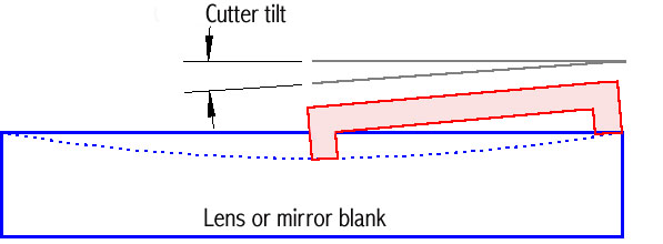
One way to make a 60" concave radius in a piece of glass is to make a 60" radius bar with a powered grinder on one end. This become very awkward as the radius increases. Another way is to use a ring shaped cutter at an angle to the glass.
Imagine a ring a few inches in diameter, held against a basketball. If you hold the ring in a fixed position, and rotate the ball about its center, it will maintain perfect contact. This basic idea is used to generate glass spheres, routinely used in the prognostication industry, and to generate spherical surfaces on glass disks for lenses or mirrors.
For simplicity, the above illustration shows a diamond cup wheel one-half the diameter of the disk, but a larger wheel actually works better. To generate a convex surface, the tilt is reversed, so that the outer edge of the grinding cup is lower than the edge at the center of the disk. Once the angle is set, the disk is rotated to produce the spherical curve.
The formula for determining the proper tilt is:
sin(tilt) = d/2R, where "d" is the diameter of the diamond cup wheel, and "R" is the radius desired on the disk.
Cutting Glass 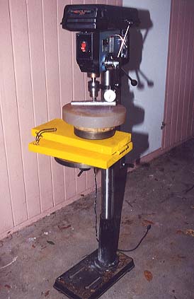
With my drill press, I decided it would be easier to tilt the glass than try to tilt the cutter. For cutting tilted elements, machinist use a "sine table", which is basically two hinged plates. I decided to try to make one out of wood and a very large hinge. I used a piece of 2"x12" for the base, and a piece of 2"x10" for the top. Like all of my recent projects, this one, too was painted in Shoptask Yellow.
A large (8" OD) bearing was used to make the
turntable, with a double layer of 3/4" plywood as a disk for mounting the
glass. To set the tilt, I made a tilt gage
out of a piece of 1" aluminum round stock, a 1/2" pin in the center,
and hole at 3" for a dial indicator. After some work in the lathe to
get rid of the runout, I chucked it into the drill press. Rotating one
revolution yields the change in height over a distance of 6.00 inches, which of
course measures the tilt.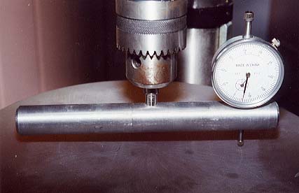
Here's a spreadsheet to calculate all of this.
For my first attempt, I used a 12" disk of CerVit,
which had a very shallow curve, but I wanted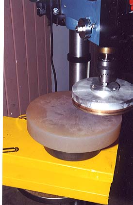 to grind it out to a 152" radius. The setup involves rotating the
drill press head and the table, to get the centerline of the drill press on the
centerline of the hinge, and the edge of the cup over the center of the blank.
It sounds complicated, but a few minutes experience makes it fairly easy.
In the photo at right, you can see that the offset and rotations aren't yet
adjusted.
to grind it out to a 152" radius. The setup involves rotating the
drill press head and the table, to get the centerline of the drill press on the
centerline of the hinge, and the edge of the cup over the center of the blank.
It sounds complicated, but a few minutes experience makes it fairly easy.
In the photo at right, you can see that the offset and rotations aren't yet
adjusted.
When cutting, one hand works the drill press, the other hand sprays coolant (soluble oil and water) from a mist bottle, and the other hand rotates the disk. I used about 600 rpm on the cutter, and fed the disk gently into the glass, slowly grinding the curve out to the edge. CerVit is fairly hard, so I went easy and used a lot of coolant.
My first attempts at sticking the glass to the turntable used Velcro, but it had too much flex, and allowed the disk to deflect when grinding. I ended up with a curve about 20" too short, which I attributed to the flex of the Velcro.
My second attempt, pictured here, used pitch to fasten the disk down. This failed on two counts. First, it sets up too fast to allow satisfactory centering of the disk. Secondly, it released while grinding, sending the disk flying through the air! By a million-to-one chance, I was able to snatch the oiled disk out the air before it hit the ground! Here's the lucky disk, with a nice curve ground in it. Generating the curve took about 20 minutes.
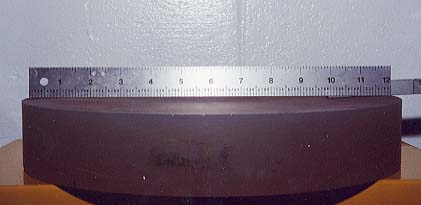
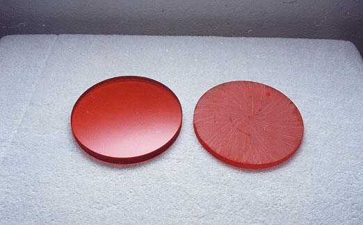
I decided to abandon pitch, and go with something simpler on my next attempt: tape. I needed to generate a shallow convex curve on a 5.8" disk of red glass, so I made a 5.8" disk out of some scrap plywood, and screwed that down to the 8" turntable. I then taped the glass disk to the plywood support, using 1" width fiber reinforced shipping tape. Four layers held the disk very firmly, with less than .010 runout.
The grinding went very quickly, but to my dismay, the curve was too strong again, about 25% shorter than I wanted. I reset the tilt to about 2/3rd's of the calculated value, and recut. Now, it was about 20% too long! Finally, I decided to just use it as is, and grind it a bit to get the proper radius.
I checked the setup to insure that the sine table isn't tilting side to side, as well as front to back, which I suspected was a large part of the error. Finally, I found the source of the error: I has entered the wrong diameter for the tilt gage into my spreadsheet. After seeing it a dozen times, I had just come to accept it as "right". After eliminating everything else, a second's work with a ruler showed the source of the error.
Replacing the incorrect value in my spreadsheets with the correct one shows that I can generate radii to within a few percent of the target, with little or no wedge.